ST-120-3 11
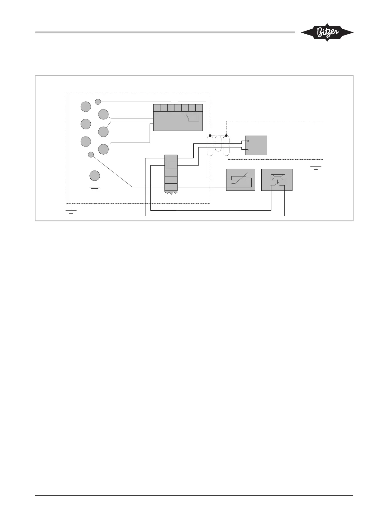
7.1.3 HS.53 .. HS.74: Connection of the protection
devices SE-E1 / SE-E3 with OFC
1
2
3
4
5
R2
F7
7
T1
1
T2
SL
2
3
8
9
Anschlusskasten / Terminal box / Boîte de raccordement
Schaltschrank / Switch / Armoire électriquecabinet
schwarz/black/noir
braun/brown/
marron
blau/blue/bleu
N
1
14
11
12
L
2
SE-E1 /
SE-E3
OFC
2
1
Fig.4: HS.53 .. HS.74 screw compressors: Example showing the connection of SE-E1 / SE-E3 in the terminal box and OFC in the switch cab-
inet
Legend see chapter Schematic wiring diagrams, page
9.
 Loading...