ST-120-3 5
3 Overview and technical data
The following table shows the product range of the
standard protection devices for BITZER screw com-
pressors and provides a short summary of the monitor-
ing functions. Each protection device is assigned to a
compressor series in which it can be used.
Protec-
tion
device
for com-
pressors
PTC con-
trol circuit
Monitoring of Fixation
Rotation
direction
Phase fail-
ure
Phase sym-
metry
Oil man-
agement
Cyc-
ling
rate
SE-E1 HS.
CSH,
CSW
① ①
5s / start
①: 3x
within
18min
①: 10x
within 24h
--- --- --- ③ / ④
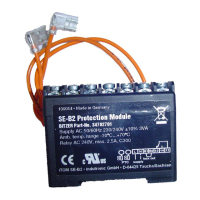
SE-E2 VSK ①: 3x
within 2h
②
①
6s / start
①: 4x
within 2h
①: 11x
within 24h
②
①: 4x
within 2h
①: 11x
within 24h
②
--- --- ③ / ④
SE-E3 HS.
CSH,
CSW
① ①
5s / start
①: 3x
within
18min
①: 10x
within 24h
--- --- --- ③ / ④
SE-B2 HS.
OS.
--- --- --- --- ①
+K1T and
C1
--- ③ / ④
OFC HS.
OS.
--- --- --- --- ① --- ③
SE-i1 HS.53 ..
HS.85
CS.65..
CS.95
✔
⑥
✔
⑥
✔
⑥
--- ✔
⑥
✔
⑥
③
Tab.1: Overview of protection devices for screw compressors
K1T Time relay for oil flow monitoring C1: Electrolytic capacitor
Tab.2: Legend
① The protection device locks immediately when the
respective limit value is exceeded.
② The protection device switches the compressor im-
mediately off when the respective limit value is ex-
ceeded and switches the compressor automatically on
when the nominal temperature is reached or, in the
case of phase monitoring, after 10min.
③ Can be fixed with screws.
④ Can be fitted on a top hat rail.
⑤ The protection device limits the time period between
two compressor starts to at least 12 minutes (sum of
running time and shut-off period) or to a shut-off period
of at least 3minutes after a longer operation time.
⑥ Further information on the complete functional range
of the SE-i1 and on data communication using BEST,
see Technical Information CT-110.
 Loading...