4
1
2
4
3
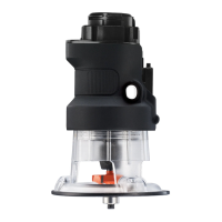
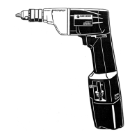
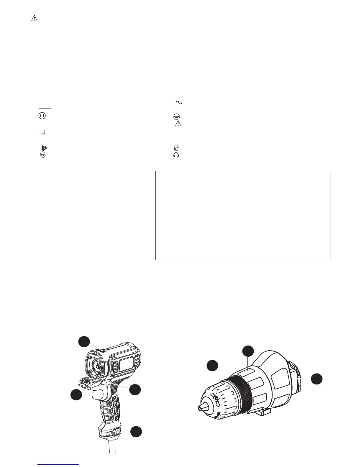
FUNCTIONAL DESCRIPTION
1. Forward/reverse slider
2. Variable speed trigger
3. Attachment release button
4. Bit holder
5. Drill/screwdriver attachment
6.Keylesschuck
7.
Torque adjustment collar
Double-endedbittip(notshown)
6
7
5
WARNING: ALWAYS use safety glasses. Everyday eye glasses are NOT safety
glasses. Also use face or dust mask if cutting operation is dusty.
ALWAYS WEAR CERTIFIED SAFETY EQUIPMENT:
•
ANSI Z87.1 eye protection (CAN/CPA Z94.3),
•
ANSI S12.6 (S3.19) hearing protection,
•
NOSH/OSHA respiratory protection.
SYMBOLS
Thelabelonyourtoolmayincludethefollowingsymbols.Thesymbolsandtheirdefinitionsareasfollows:
V ..................volts A ...................amperes
Hz ................hertz W ..................watts
min ..............minutes
................alternating current
............. direct current
n
o .................no load speed
................Class I Construction ..................earthing terminal
(grounded)
................safety alert symbol
................Class II Construction .../min or rpm...revolutions or
(double insulated) reciprocation per minute
............
Read instruction manual before use
..................Use proper respiratory protection
................Use proper eye protection ..................Use proper hearing protection
Whenusinganextensioncord,be
sure to use one heavy enough to carry
the current your product will draw. An
undersized cord will cause a drop in line
voltage resulting in loss of power and
overheating. The following table shows
the correct size to use depending on
cord length and nameplate ampere
rating.Ifindoubt,usethenextheavier
gauge. The smaller the gauge number,
the heavier the cord.
Minimum Gauge for Cord Sets
Volts Total Length of Cord in Feet
120V 0-25 26-50 51-100 101-150
(0-7,6m)(7,6-15,2m)(15,2-30,4m)(30,4-45,7m)
240V 0-50 51-100 101-200 201-300
(0-15,2m)(15,2-30,4m)(30,4-60,9m)(60,9-91,4m)
Ampere Rating
More Not more American Wire Gauge
Than Than
0 - 6 18 16 16 14
6 - 10 18 16 14 12
10 - 12 16 16 14 12
12 - 16 14 12 NotRecommended

 Loading...