Analog detectors and bases Mounting | en 7
Bosch Security Systems, Inc. Installation Guide 2018.08 | 6.0 | F.01U.123.589
2. Tighten the base to the mounting surface. Do not over tighten. If you use a 6-inch base, fit
the base skirt onto the mounting base.
3. Turn clockwise until the detector head locks into place and aligns with the semi-circle
notch (4).
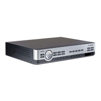
3.2 Locking and Releasing the Detector
The detector bases are supplied with a snap-off locking bar (X) as part of the base moulding
to prevent malicious removal of the detector. The locking mechanism is selectable and is
activated by shifting the U-shaped locking bar (X) into the position as shown.
1. Remove the U-shaped locking bar by breaking it from its holder.
2. Tuck it into the opening next to it by pushing hard.
3. Insert the detector head into the base.
Figure3.2: Activating the Locking Mechanism
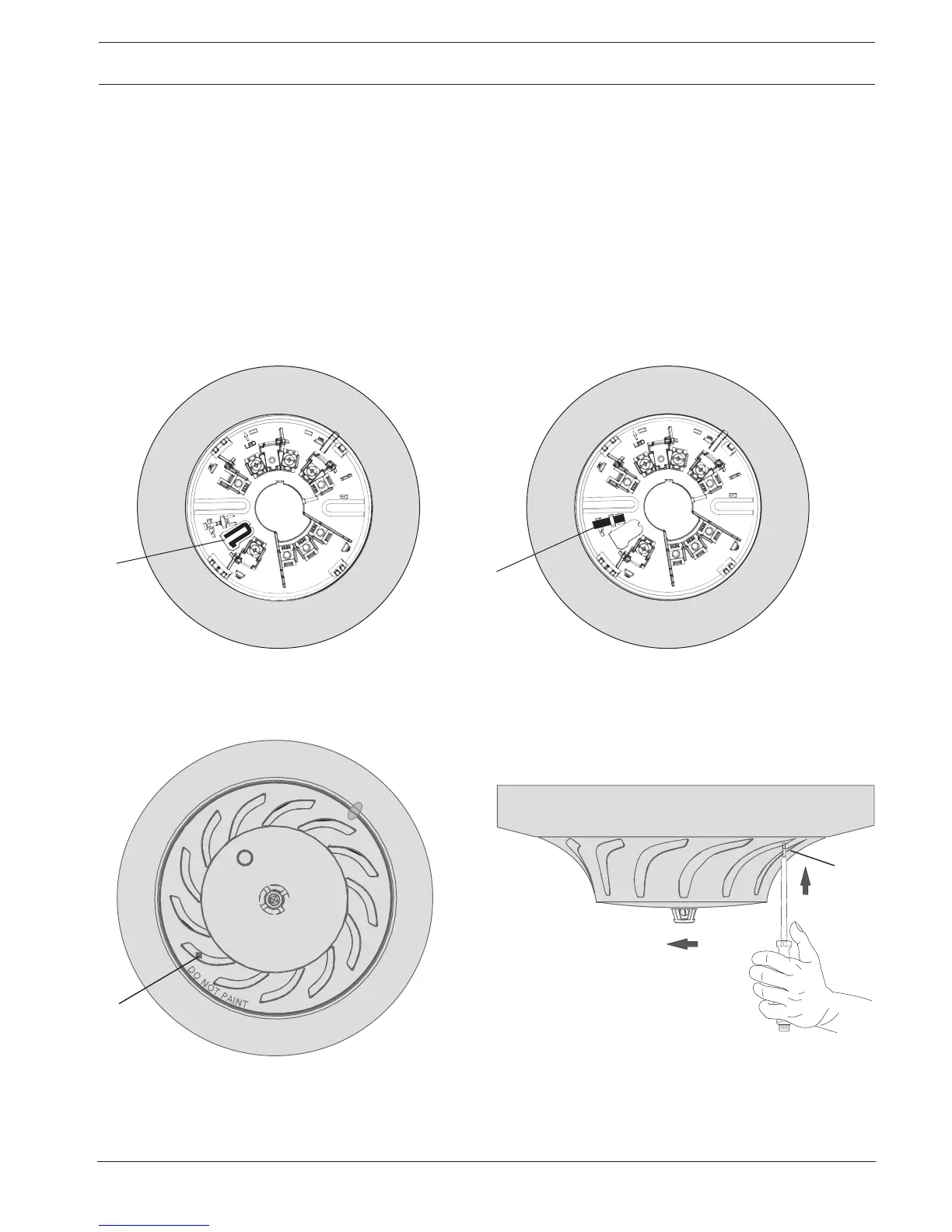
4. Release the locked detector head by pushing hard through the dimple (O) on the
detector’s outer rim with a screwdriver and at the same time, turning the detector head
to the left.
 Loading...