EasyManua.ls Logo

Bosch 440 Series User Manual

Bosch 440 Series
44 pages
To Next Page IconTo Next Page
To Previous Page IconTo Previous Page
Page #8 background imageLoading...
Page #8 background image
8 en | Wiring and Addressing Information Analog detectors and bases
2018.08 | 6.0 | F.01U.123.589 Installation Guide Bosch Security Systems, Inc.
4 Wiring and Addressing Information
4.1 Wiring Information
!
Warning!
Do not twist or loop the wires around the terminals. In and out wires for terminal connection
must be cut, stripped, and inserted as individual ends.
The following wire gauges and maximum line lengths are tested and approved.
18 AWG (0.8 mm
2
) -> 4000 ft. (1200m)
16 AWG (1.3 mm
2
) -> 6225 ft. (1900m)
14 AWG (2.1 mm
2
) -> 7200 ft. (2200m)
12 AWG (3.3 mm
2
) -> 9850 ft. (3000m)
Standard non-twisted, non-shielded wiring (plain old wire) for the SLCs is recommended.
Notice!
Voltage drop calculations along with anticipated wire distance should be considered to
ensure a voltage supply of at least 24 V at every detector.
Terminal Lettering Terminal Function
SC SLC bus - IN/OUT
S SLC bus + IN/OUT
S
in
SLC bus + IN
S
out
SLC bus + OUT
C Remote output
+
+
S
C
SC
S
C
SC
SC
SC
SC
SC
S
S
S
S
Figure4.1: FAA-440-B6/-B4 Standard Base Class B Wiring (Class A Wiring Indicated by Dashed Wire)

Other manuals for Bosch 440 Series

Question and Answer IconNeed help?

Do you have a question about the Bosch 440 Series and is the answer not in the manual?

Bosch 440 Series Specifications

General IconGeneral
Hard Drive Support1 SATA HDD
Operating SystemEmbedded Linux
CompressionH.264
Motion DetectionYes
Audio Output1 channel
Mobile ViewingYes
Network ConnectivityEthernet
Operating Temperature14°F to 131°F (-10°C to 55°C)
Video Input4 channels

Summary

Notes

Product Types

Mounting

Mounting the Detector

Details the process for attaching the detector to the mounting base, including skirt removal.

Locking and Releasing the Detector

Explains how to secure and detach the detector head from its base using the locking mechanism.

Wiring and Addressing Information

Wiring Information

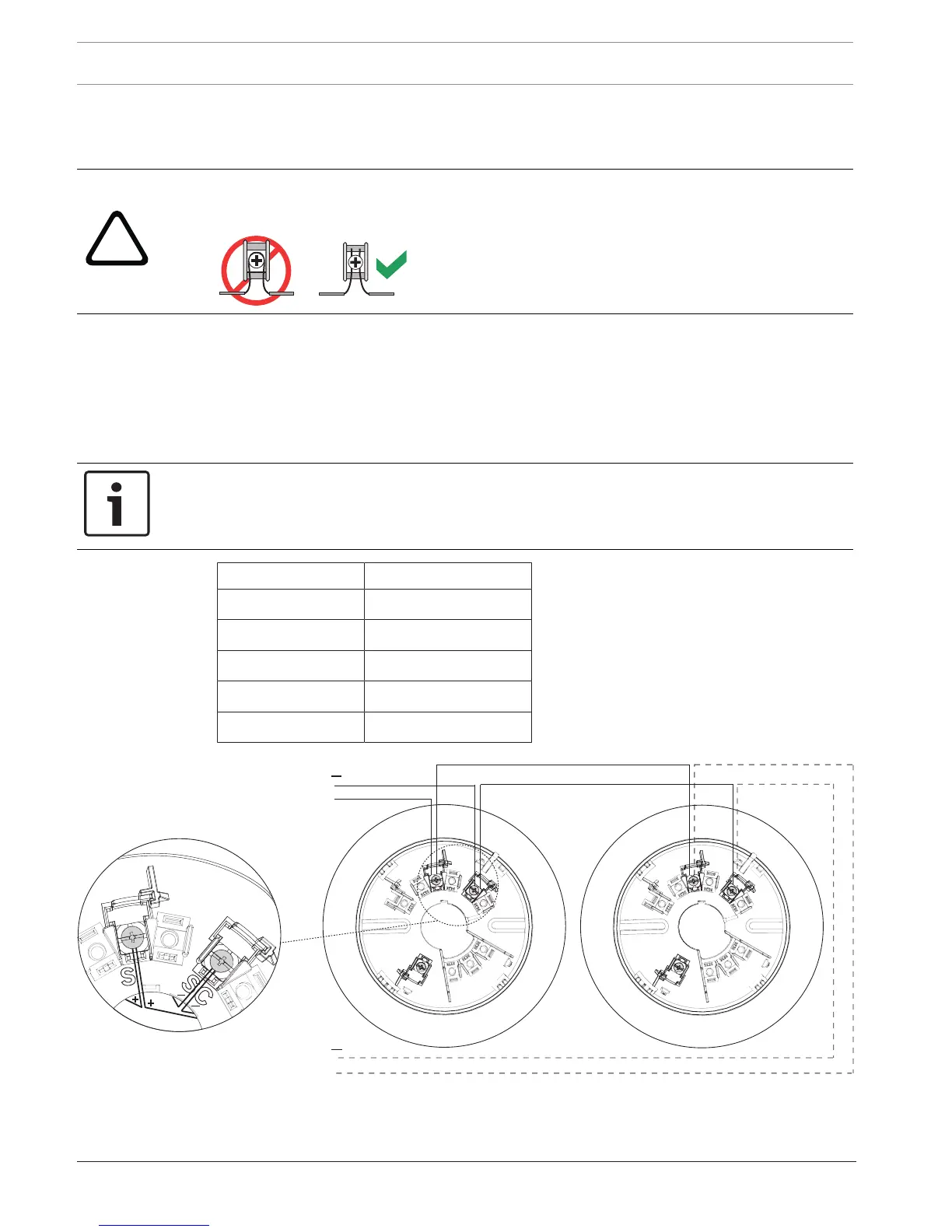
Provides guidance on wire gauges, lengths, and terminal functions for detector connections.

Addressing Information

Describes how to set the detector's address using rotary switches on the device.

Testing the Installation

Magnet Switch Test

Details the procedure for testing the detector's alarm function using a magnet.

Functional Testing

Outlines methods for verifying detector operation, including walk test and specific tests.

Specifications

Related product manuals