ACS 753, ACS 763, ACS 863 Service Manual
SP00D00609 2018-03-26Robert Bosch GmbH
71
Electrical
Replacing Load Cells
WARNING: Disconnect the unit from
the power source before beginning
service work. Incorrect use or
connections can cause electrical
shock.
WARNING: Wear safety goggles
when working with refrigerants.
Refrigerants can cause eye injury.
WARNING: Use extreme caution
when disconnecting hoses.
Pressurized refrigerant may be
present in hoses. Point hoses away
from you and anyone nearby.
Instructions
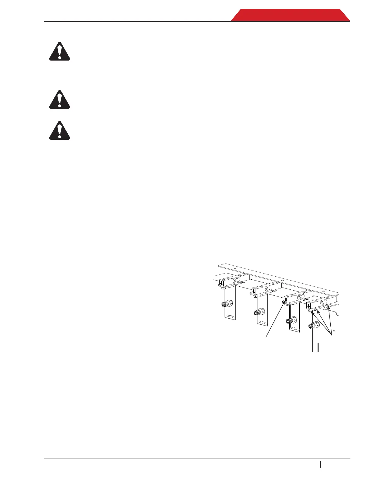
These general instructions outline the steps to
replace the oil drain, PAG or POE, or dye load
cells. See Figure 3.10.
Removing the Load Cell
1. Disconnect the unit from the power source.
2. Remove the oil (PAG and POE), dye, and
drain bottles from the load cells.
3. Remove the HMI frame and back panel.
4. Disconnect the wire harness connecting the
load cell(s) being replaced from the control
board.
5. Remove the 4 screws securing the load cell
to adapter block (internal side of the panel
and outside the panel, see picture).
6. Remove the load cell.
Installing the Load Cell
1. Connect the new load cell to the adapter
block and secure in place with screws
(arrow going down see picture).
2. Be sure adapter or load cells don’t toching
the external frame.
3. Connect the load cell wire harness to the
control board.
4. Close the HMI back panel and put the frame.
5. Connect the unit to its power source and
turn the unit on. Press the MENU icon.
6. Select the SERVICE MENU.
7. Enter yearly password and select OK icon.
8. Select the Up or Down arrow key to scroll
to CALIBRATIONS and select OK icon.
9. Scroll to the load cell requiring calibration
and and select OK icon.
10. The process of calibrating the load cells
involves two weights. The rst is the un-
loaded load cell (0.0 grams), the second
is with a weight hanging from the load cell
(500 grams) Pause between each calibra-
tion step to make sure the values are loaded
into the data set.
11. Double check with sample weight of
250 grams is needed to complete calibra-
tion After entering, select OK icon.
Figure 3-10. Load cells
Screws
Cell mounting
direction

 Loading...