ACS 753, ACS 763, ACS 863 Service Manual
SP00D00609 2018-03-26 Robert Bosch GmbH
76
Plumbing and Mechanical
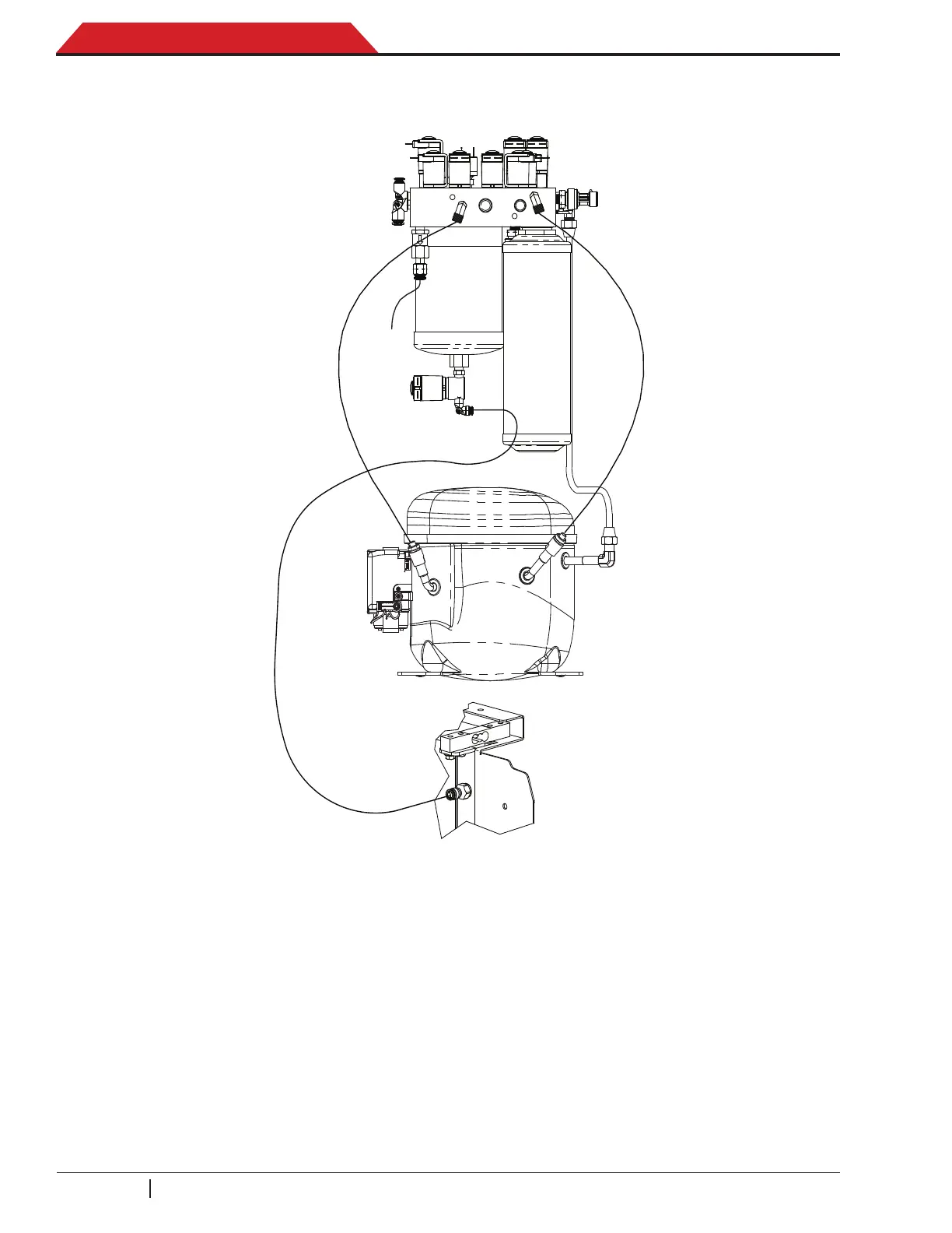
Figure 4-1. Compressor Interconnection Diagram
NOTES:
1. Adjust position of ISV liquid and vapor hoses so that the hoses do not contact the center
divider or vacuum pump shelf.
2. Apply Loctite 242 to equivalent to threads.
3. Torque hose ttings to 8.5 ±0.5Nm.
4. Route replacement hoses and tubes in the same positions and places as the original securing
with tie-wraps where appropriate.
MANIFOLD ASSEMBLY
COMPRESSOR
OIL DRAIN ASSEMBLY
 Loading...