Installation Instructions Bosch IDS BOVB 18 | 15
Bosch Thermotechnology Corp. | 10.2020
Data subject to change
11 Electrical - Low Voltage
11.1 Low Voltage Maximum Wire Length
Table 4 defi nes the maximum total length of low voltage wiring from the outdoor
unit, to the indoor unit, and to the thermostat.
24 Volts - Wire size Max. Wire Length
18 AWG 150 Ft.
16 AWG 225 Ft.
14 AWG 300 Ft.
Table 4
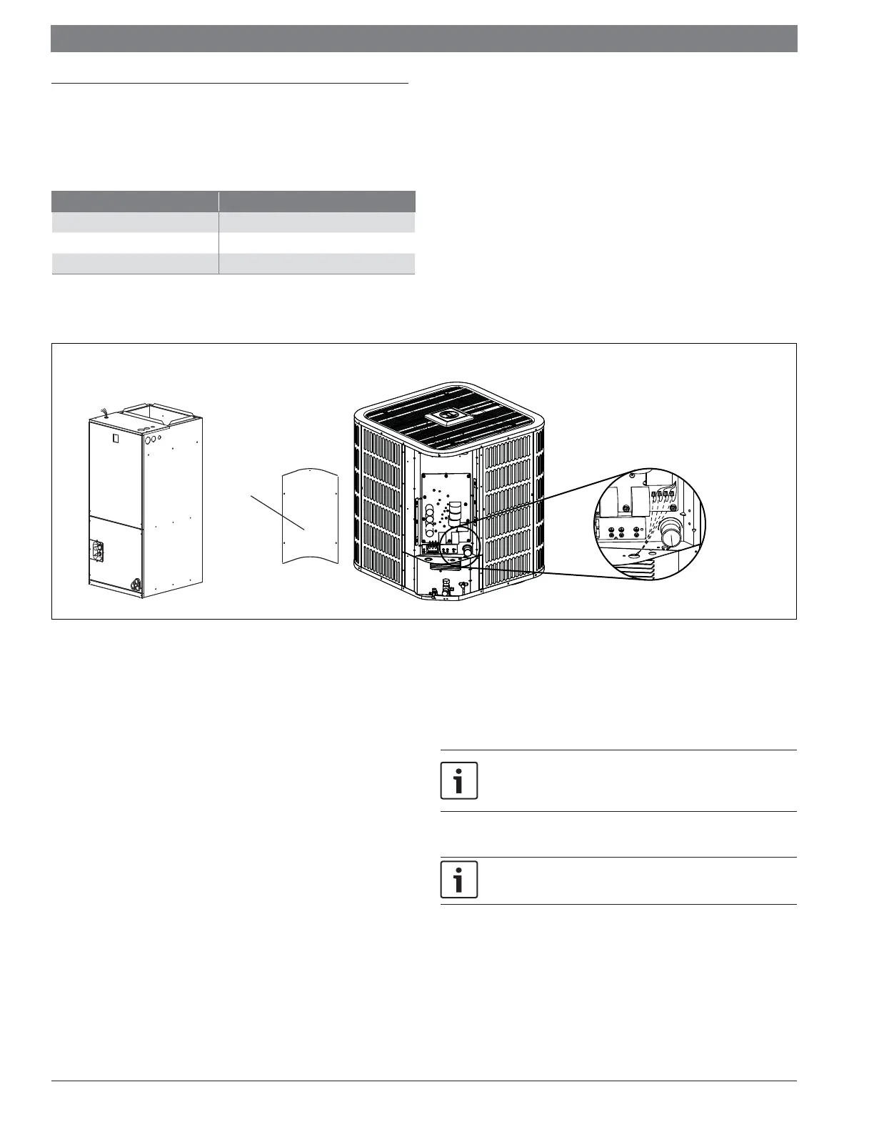
11.2 Low Voltage Hook-Up Diagrams
Figure 24
Control
Board
Access
Panel
NOTES:
- Low voltage connection must be made inside the
outdoor unit control board access panel.
- There is no terminal block for low voltage connections,
wires must be spliced using field supplied wire nuts
- Field supplied wire nuts should be 22-16 gauge.
- Refer to unit wiring diagram for more information.
Low Voltage Unit Connections
11.3 Thermostat Wiring Diagrams
Be sure power supply agrees with equipment nameplate.
Power wiring and grounding of equipment must comply with local codes.
Low voltage wiring to be minimum No. 18 AWG conductor.
“- - - - - - - -” represents Field installed electric auxiliary heat connection
Single-stage auxiliary heating supported by 2H thermostat
Twin-stage auxiliary heating supported by 3H thermostat
W1: The first stage of field installed electric auxiliary heat.
W2: The second stage of field installed electric auxiliary heat.
The outdoor unit W signal is connected to first or second stage electric
auxiliary heat.
Dashed lines in the following thermostat wiring diagrams refer to optional
wiring (wiring for Electric Heat). For thermostat wiring please refer to the
Owner’s Manual of the thermostat.
B terminal to be connected with thermostat (O/B) wiring. Reversing valve
energizes in heating.
 Loading...