Installation Instructions Bosch IDS BOVB 18 | 25
Bosch Thermotechnology Corp. | 10.2020
Data subject to change
15 System Operation and Troubleshooting
15.1 Control Logic Description
The variable speed system adopts the same 24VAC control as any conventional
heat pump.
The compressor’s speed is controlled based on coil pressures monitored by
the unit's pressure transducer. To ensure stable and adequate capacity, the
compressor speed will modulate relative to evaporator pressure during cooling
operation and relative to condensing pressure during heating operation. The
target pressure can automatically adjust based on compressor operation so
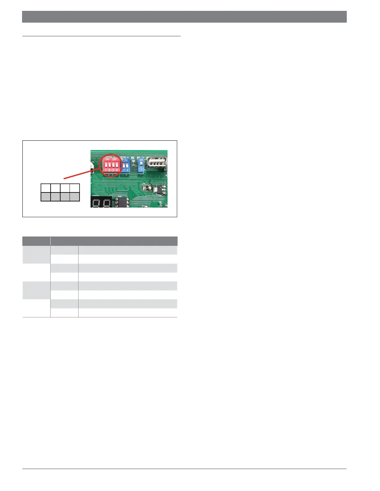
optimal capacity can be achieved. Target pressure can be manually adjusted
(SW4) to achieve improved dehumidification and capacity demands.
Figure 43
ON
OFF
1 2
3 4
SW4
Switch Description
SW4-1
ON Unused
OFF* Must be set at "OFF" position
SW4-2
ON Unused
OFF* Must be set at "OFF" position
SW4-3
ON Adaptive capacity output disabled
OFF* Adaptive capacity output enabled
SW4-4
ON Accelerated cooling/heating
OFF* Normally cooling/heating
Table 11
*Factory Default
Adaptive capacity function is a "self-learning function" which allows a range
of target coil temperatures to adapt for better unit operation and reduced
short cycling.
Accelerated cooling/heating function changes the initial target coil
temperature to provide "enhanced comfort" by increasing unit capacity.
15.2 Sensors (Thermistors/Pressure Transducer)
T3 = Outdoor Coil Temperature (Table 24)
— High/Low temperature protection
— Outdoor fan control (cooling mode)
— Defrost control (heating mode)
T4 = Ambient Temperature (Table 24)
— Operating condition permission
— Defrosting condition permission
— Outdoor fan control (heating mode)
T5 = Compressor Discharge Temperature (Table 25)
— High/Low temperature protection
— Electronic Expansion Valve (EEV) (ODU/heating mode only)
TF = IPM Radiator Temperature
— Inverter High Temperature Protection
Pressure transducer
— Compressor frequency control
— Electronic Expansion Valve (EEV) control (heating mode only)
— High pressure protection (heating mode)
— Low pressure protection (cooling mode)
15.3 Pressure Equalizer Valve (PEV)
Used to balance the pressure in the system before compressor start up.
15.4 Defrost Description
The Demand Defrost Control (DDC) monitors the ODU coil temperature
using thermistor (T3). A second thermistor (T4) monitors outdoor ambient
temperature. Based on these parameters, as well as accumulative run time
and high pressure, the DDC calculates proper initiation of defrost.
Any one of the below three conditions is required to enter defrost:
1. The calculated temperature difference between the outdoor temperature
(T4) and the coil temperature (T3) is called Delta T. After Delta T is
achieved and continues for 3 minutes.
— T4 ≥ 39°F, Delta T = 18°F
— T4 ≥ 30°F, Delta T = 16°F
— T4 ≥ 19°F, Delta T = 14°F
— When T4 < 19°F, T3 < 9°F, accumulative compressor run
time ≥ 80 minutes.
2. After “Minimum Run Time” (MRT) is achieved. MRT is based on outdoor
ambient temperature (T4), for example:
— MRT is 4 hours when: T4 < 23°F
— MRT is 2 hours when: 23°F ≤ T4 < 40°F
3. After the high pressure saturation temperature drops below 82°F for 20
minutes.
Defrost will terminate once outdoor coil temperature (T3) reaches 64°F for
a period of 1 minute or defrost time has exceeded 8 minutes.
 Loading...