10 Climate 5000 – 6720886909 (2018/04)
Indoor Unit Installation
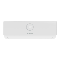
Wall
Indoor Outdoor
5-7mm
Fig. 4.
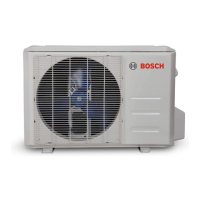
Mounting plate dimensions
Different models have different mounting plates. In order to ensure that
you have ample room to mount the indoor unit, the diagrams to the
right show different types of mounting plates along with the following
dimensions:
• Width of mounting plate
• Height of mounting plate
• Width of indoor unit relative to plate
• Height of indoor unit relative to plate
• Recommended position of wall hole (both to the left and right of
mounting plate)
• Relative distances between screw holes
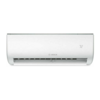
Correct orientation of Mounting Plate
Fig. 5.
Model A
Left rear wall
hole 65mm
Right rear wall
hole 65mm
Indoor unit
outline
398mm
715mm
233.1mm
146.5mm
285mm
45mm 101.6mm 115.6mm
47.1mm
47.1mm
39mm
39mm
117.5mm
Fig. 6.
Model B
Left rear wall
hole 65mm
Right rear wall
hole 65mm
Indoor unit
outline
398mm
805mm
241mm
228.5mm
285mm
45mm 183.6mm 123.6mm
47.1mm
47.1mm
39mm
39mm
117.5mm
Fig. 7.
Model C
Left rear wall
hole 65mm
Right rear wall
hole 65mm
Indoor unit
outline
439mm
958.3mm
224.2mm
228.5mm
285mm
45mm
259.1mm
100.6mm
47mm
47.5mm
36.7mm
36.6mm
123.7mm
Fig. 8.
Model D
Left rear wall
hole 65mm
Right rear wall
hole 65mm
506mm
1037.6mm
291mm
316.7mm
324.9mm
47mm
47mm
55mm
55mm
246mm271.7mm
Fig. 9.
NOTE
When the gas side connective pipe is Ø16mm or more, the wall hole
should be 90mm.
1.4 Step 4: Prepare refrigerant piping
The refrigerant piping is inside an insulating sleeve attached to the back
of the unit. You must prepare the piping before passing it through the
hole in the wall. Refer to the Refrigerant Piping Connection section
of this manual for detailed instructions on pipe flaring and flare torque
requirements, technique, etc.
1. Based on the position of the wall hole relative to the mounting plate,
choose the side from which the piping will exit the unit.
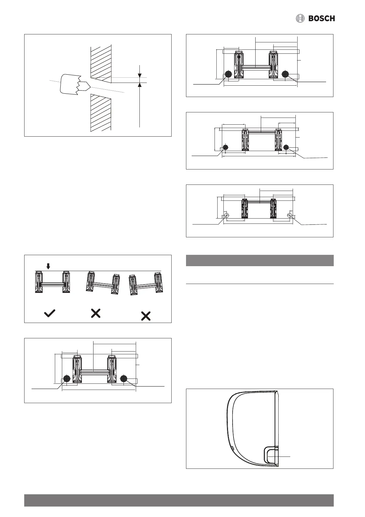
2. If the wall hole is behind the unit, keep the knock-out panel in place.
If the wall hole is to the side of the indoor unit, remove the plastic
knock-out panel from that side of the unit. (See Fig. 10). This will
create a slot through which your piping can exit the unit. Use needle
nose pliers if the plastic panel is too difficult to remove by hand.
Knock-out Panel
Fig. 10.
 Loading...