Technical information
Compress 3000 AWES – 6720892204 (2020/06)
32
11.3.6 EVU/SG wiring diagram for the indoor unit with an
integrated electric booster heater
11.3.7 Photovoltaic
Since there are only two external inputs for the energy supplier and PV,
these cannot be used at the same time.
PV connection to external input 1 or 4.
The heat pump is able to process a control signal of a PV system.
If the PV system has sufficient current for operating the heat pump, it can
communicate this information to the heat pump in the form of a start
command via a control cable. The control cable must be connected to
one of the available external connections. The selected external
connection must be configured in the control unit for the PV function.
The heating system must have a buffer cylinder and only heating circuits
with a mixer in order for a start command to be effective. A start
command causes the buffer cylinder to be charged up to the maximum
temperature achievable by the heat pump. However, it can only be
charged when the temperature in the buffer cylinder is below the
maximum temperature. Otherwise, the heat pump remains off.
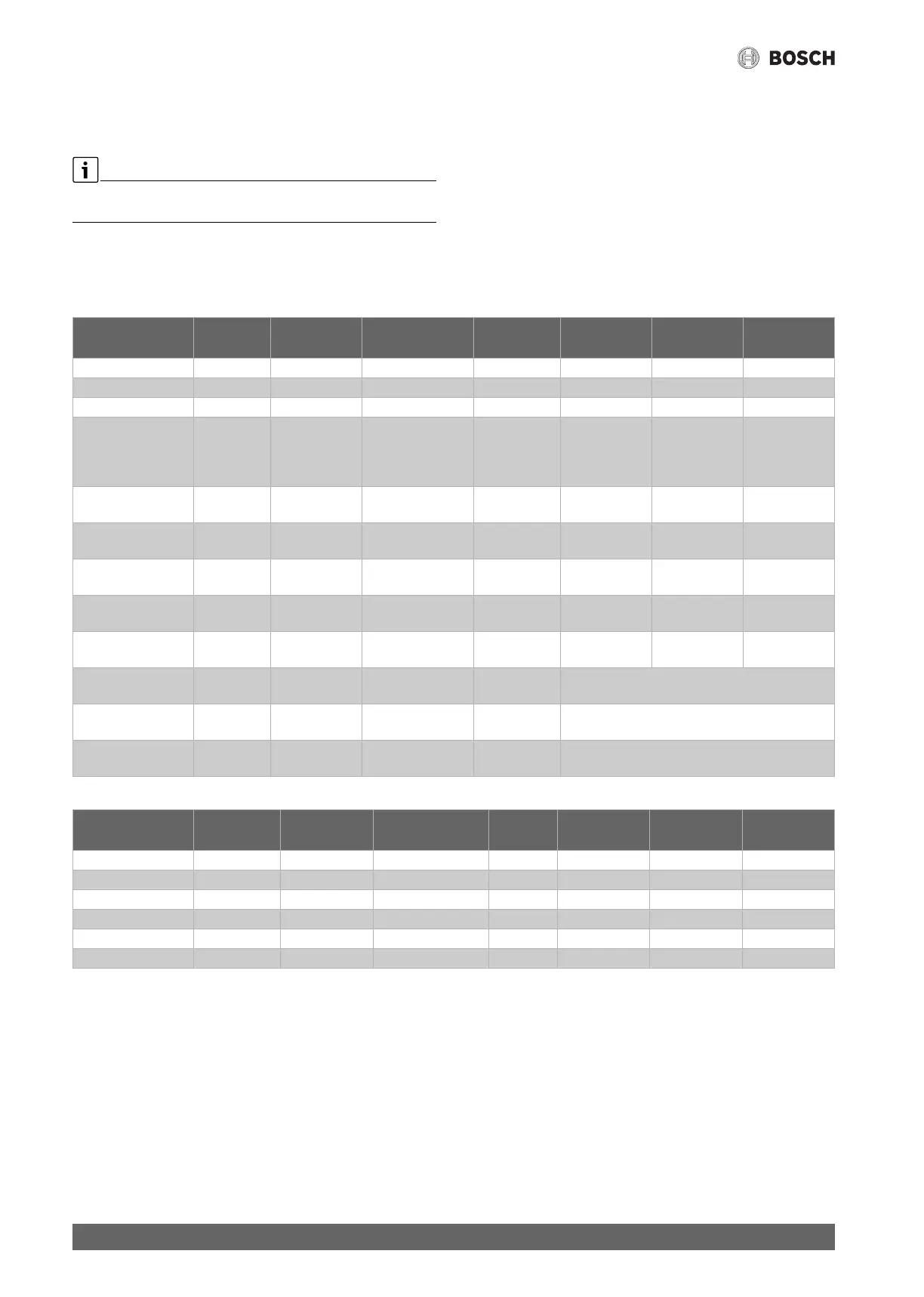
11.4 Kabelplan
Table 11 Connections in indoor units IDU AWE/AWM/AWMS and AWB
Table 12 Cable plan sensor
11.5 Measurements from temperature sensors
Designation min. cross-
section
type of cabel max. length connected at: connection
terminal:
Power source
3-way valve VW1 3 x 1,5mm² cable integrated Indoor unit 53 / 54 / N IDU
Pump 1. HC PC1 3 x 1,5mm² H05VVF Indoor unit 52 / N / PE
DHW pump PW2 3 x 1,5mm² H05VVF 58 / N / PE
Signal cable IDU - ODU CAN-BUS 2 x 2 x 0,75mm
2
LIYCY (TP) 30m Can High 31(H)
Can Low 32(L)
12V not
connected
2-wire
connection,
shielding in both
ends
Power supply IDU AWE/
AWM/AWMS
5 x 2,5mm² NYY Indoor unit sub-distribution
3 x C16
Power supply IDU AWB 3 x 1,5mm² NYY Indoor unit L / N / PE sub-distribution
1x C16
Heating cable 3 x 1,5mm² NYY 3m Indoor unit 56 / N / (HC /
HC)
IDU / HC / HC
EMS - Module MM100,
MS100..
0,5mm² J-Y (ST)Y 2 x 2 x 0,6 100m Indoor unit 19 / 20
0-10V control boiler EM0 2 x 2 x 0,75mm
2
LIYCY (TP) Indoor unit
(IDU AWB)
38 / 39
PV-Function 0,4mm² J-Y (ST)Y 2 x 2 x 0,6 From inverter on terminal I1 or I4 in IDU,
EVU-block or Smart Grid
Smart Grid 0,4mm² J-Y (ST)Y 2 x 2 x 0,6 From load management controller on terminal I4,
connection 49, 50 in IDU
EVU-block 3 x 1,5mm² H05VVF From load management controller on terminal I1,
connection 13, 14 in IDU
Sensor Designation min. cross-
section
type of cabel max.
length
connected at: connection
terminal:
Power source
Outdoor T1 0,5 mm
2
J-Y (ST)Y 2 x 2 x 0,6 Indoor unit 3 / 4
Flow T0 0,5 mm
2
J-Y (ST)Y 2 x 2 x 0,6 Indoor unit 1 / 2
Hot water (DHW) TW1 0,5 mm
2
J-Y (ST)Y 2 x 2 x 0,6 Indoor unit 5 / 6
Dew sensor MK2 (max. 5x) 0,5 mm
2
cable integrated Indoor unit 34 / 35
Mixed heating circuit TC1 0,5 mm
2
J-Y (ST)Y 2 x 2 x 0,6 100m MM100 1 / 2
Pool temperature TC1 0,5 mm
2
J-Y (ST)Y 2 x 2 x 0,6 100m MP100 1 / 2
 Loading...