Preparing for installation
Compress 3000 AWES – 6720892204 (2020/06)
6
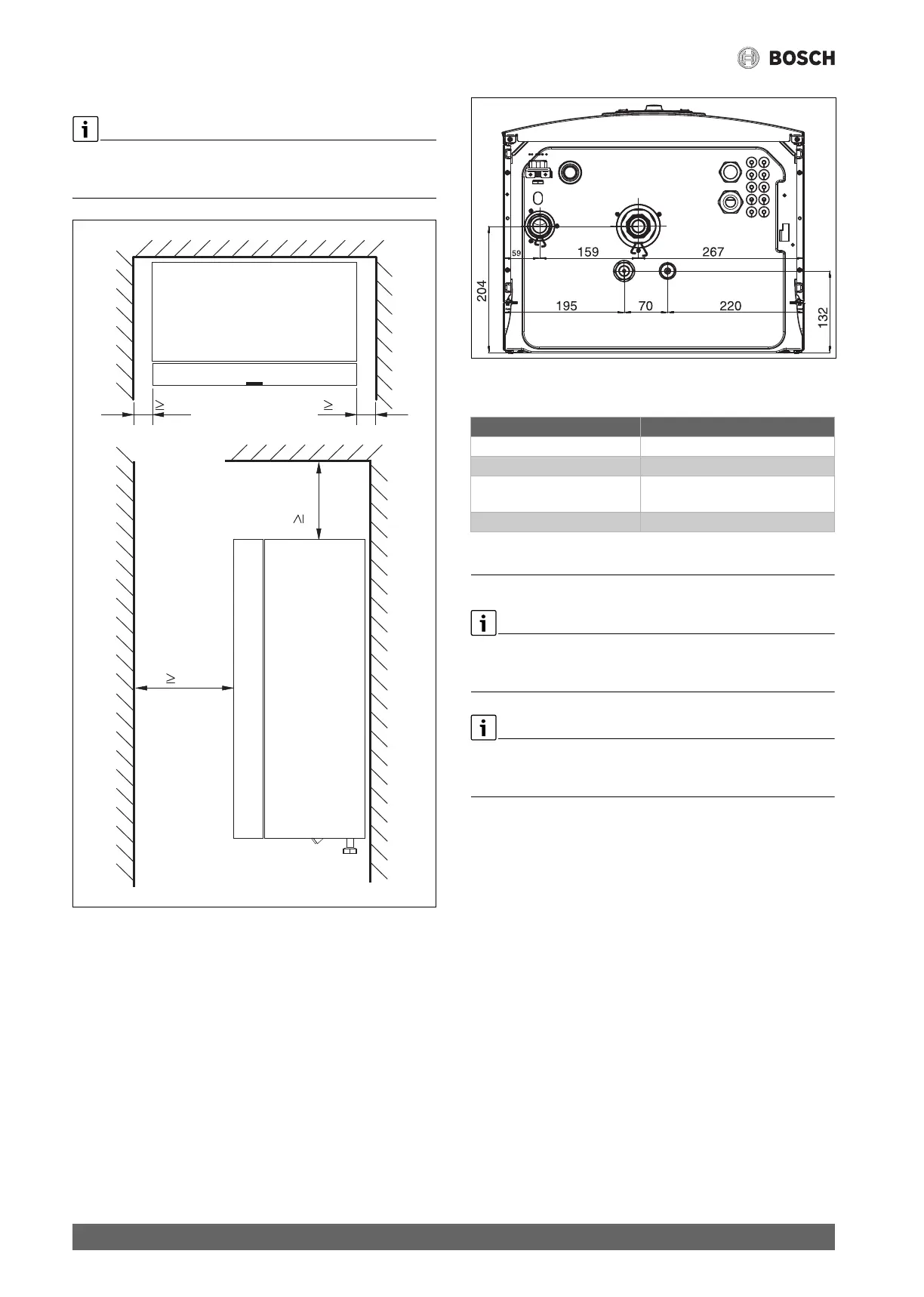
3.6 Product dimensions and minimum clearances
Mount the indoor unit high enough so that the control unit is easy to use.
In addition, take into account pipes and connections under the indoor
unit.
Fig. 3 Minimum distance (mm)
Fig. 4 Dimensions and connections
3.7 Pipe dimensions
Table 4 Pipe dimensions
4Preparing for installation
The particle filter is installed horizontally in the heating system return
upstream of the inlet of the indoor unit. Note the direction of flow of the
filter.
The drain pipe of the pressure relief valve in the indoor unit must be
installed so that it is protected against frost, and the drain pipe must be
routed to the drain.
▶ Run the connector pipes for the heating system and cold/domestic
hot water in the building up to the installation location of the indoor
unit.
4.1 Assembly of the indoor unit
• Mount the indoor unit on a suitable wall within the house. The length
of piping between the outdoor unit and indoor unit must be as short
as possible. Use insulated pipes.
• Water discharged from the pressure relief valve should be routed
away from the indoor unit to visibly terminate in a frost-free outlet.
• The installation location for the indoor unit must have a drain.
4.2 Checks prior to installation
• Check that all pipe connections are intact and have not come loose
during transportation.
• Before commissioning the indoor unit, check the heating system and,
if installed, fill and vent the DHW cylinder.
• All pipework should be as short as possible.
• The low voltage cables must be routed with a minimum clearance of
100 mm from live 230 V/400 V cables.
800
50 50
550
Pipe dimensions (mm) AWES
Heating system flow 1" male thread
CH return 1" female thread
Refrigerant pipe to/from
outdoor unit
5/8" and 3/8"
Drain/discharge ø 32
 Loading...