-12-
Accessory Assembly
(Fig. 3, Fig. 4)
Only use accessories with
Maximum Safe Operating
Speed rated at least equal to the maximum
speed marked on the power tool. Accessory
running faster than their rated speed can break
and y apart, and cause injury or property dam-
age.
Do not pull the spindle
locking bar while the spin-
dle is moving. The power tool may become
damaged if you do this.
Do not use accessories that
run eccentrically. The tool
will vibrate excessively and may cause loss of
control and the accessory may burst.
Before attaching selected accessory, ensure
that the spindle, collet, collet nut, and acces-
sory shank are clean. The accessory shank must
be straight, undamaged, and an appropriate
size in relation to the collet. Grinding wheels
must be held by a backing pad and not exceed
2" in diameter.
1. Pull the Spindle Lock Bar 4 out to lock the
Spindle 3 (Fig. 3).
2. Loosen the Collet Nut 2 with the included
17 mm Wrench 14 (Fig. 3).
3. Insert the shank of the Backing Pad Acces-
sory 15 all the way into the Collet 1 (Fig.
4).
Note: For all other accessory types, ensure
that the shank is inserted a minimum of 1".
4. Firmly clamp the accessory shank by
tightening the Collet Nut 2 with the 17 mm
Wrench 14 (Fig. 4).
5. Push the Spindle Lock Bar 4 in to release
the Spindle 3 (Fig. 4).
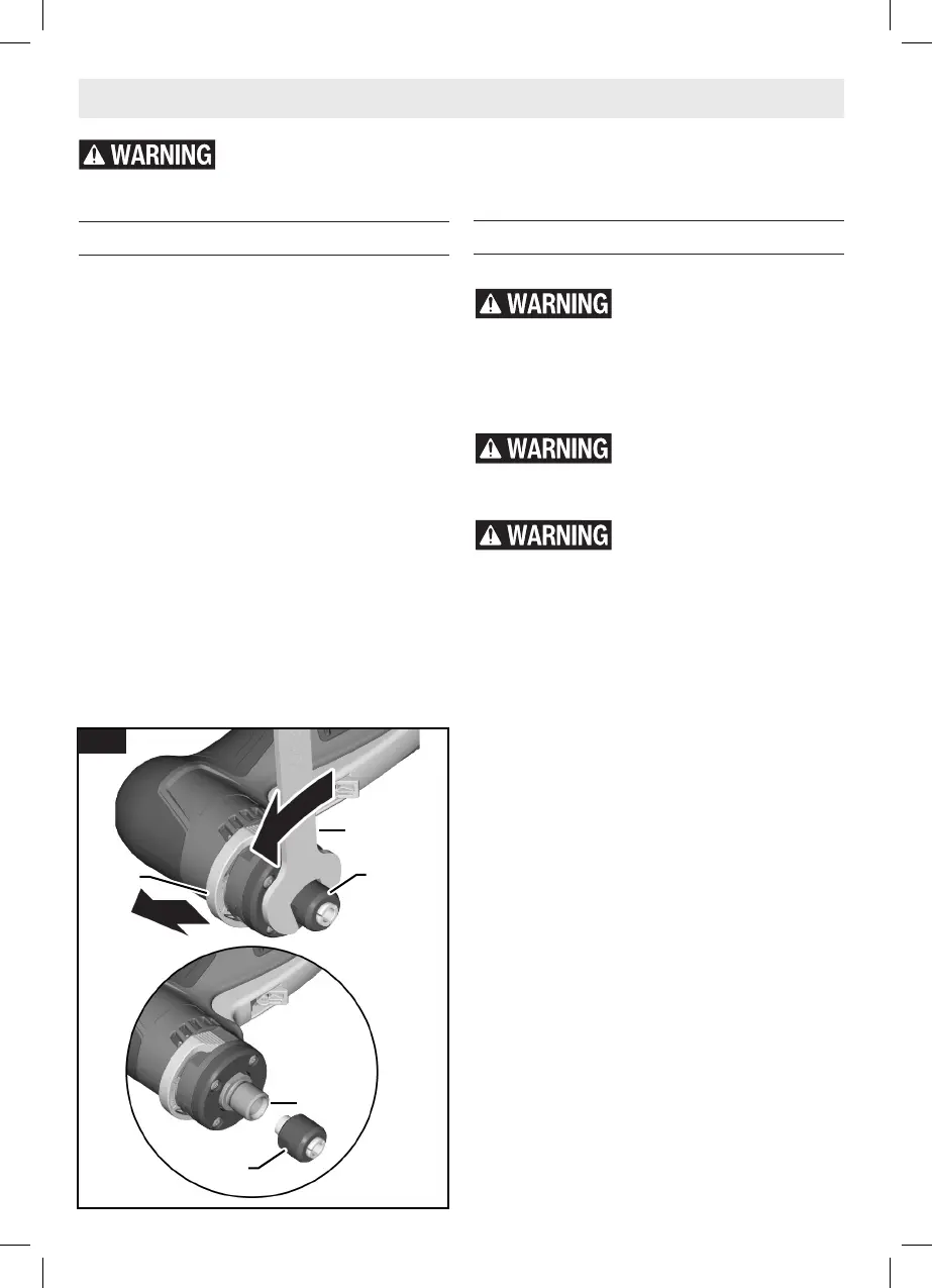
Assembly
Changing the Collet
(Fig. 2)
This tool includes a pre-installed 1/4" collet,
within the collet nut, and is to be used with a
1/4" diameter accessory shank. This assembly
may be replaced with a larger 5/16" (max size)
collet and nut assembly for 5/16" diameter ac-
cessory shanks. Consult Bosch Service Center
for selection and availability of 5/16" collet.
To replace the collet assembly:
1. Pull the Spindle Lock Bar 4 out to lock the
Spindle 3.
2. Loosen the Collet Nut 2 with the included
17 mm Wrench 14.
3. Unscrew and remove the collet and collet
nut assembly.
4. Ensure that the spindle threads are clean
and the collet is properly tted in the Col-
let Nut 2.
5. By hand, screw the new collet assembly
onto the Spindle 3.
Disconnect battery pack from tool before making any assembly, adjustments
or changing accessories. Such preventive safety measures reduce the risk of
starting the tool accidentally.
14
4 2
2
3
Fig. 2
GWG12V-20S Die Grinder OSI Final for Approval 20230627.indd 12GWG12V-20S Die Grinder OSI Final for Approval 20230627.indd 12 6/27/2023 10:52:41 AM6/27/2023 10:52:41 AM
 Loading...