2.7 Operation
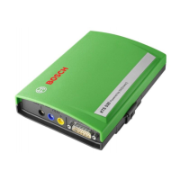
KTS 530 can only be connected with the PC/Laptop via
the USBinterface. KTS 540 and KTS 570 can be linked
with the PC/Laptop via wireless connection (Bluetooth)
or via the USB interface. Insert the Bluetooth USB
adapter in the PC/Laptop for a wireless connection.
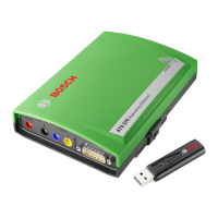
The radio connection between KTS 540/KTS 570
and the PC/Laptop can
only be made with the
Bluetooth USBadapter provided in the delivery.
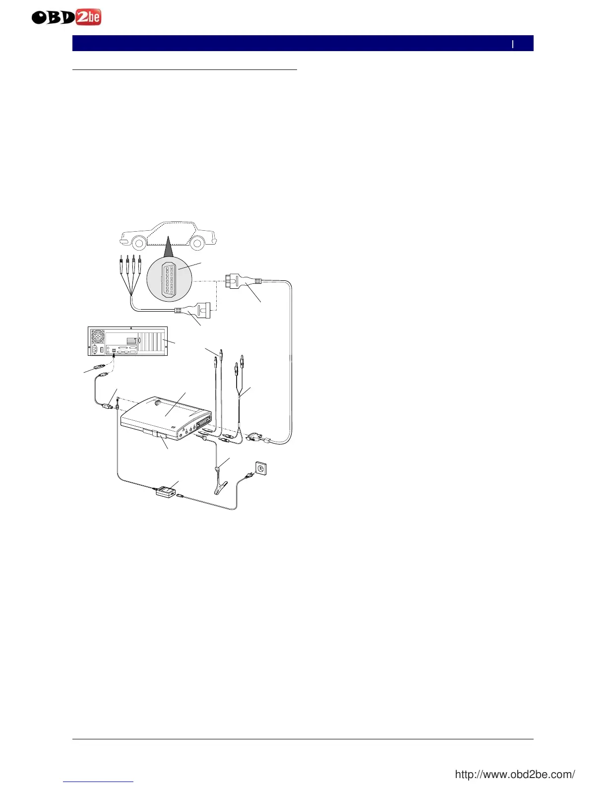
2.7.1 Connection diagram
Fig. 3 : Connection diagram in an ex ample for the KTS 570
1 OBD interface in vehicle
2 UNI connection cable
3 OBD diagnosis cable
4 Measurement cables (KTS 570)
5 Measurement cables (KTS 530, KTS 540)
6 GND lead
7 Power pack
8 Adapter insert (IBOX 01)
9 KTS 570
10 USB connecting cable
11 Bluetooth USB adapter
12 PC (Laptop)
0
2.7.2 Notes concerning controller diagnosis
KTS modules are either powered via the power
supply that is delivered or through the OBD interface
of
the vehicle.
In testing steps that require starting the motor, the
battery voltage may drop to a point that the supply is
no longer guaranteed via the vehicle. In these cases,
it may be required to supply the KTSmodule with the
power supply.
On some vehicles, the power supply through the
OBD interface may only be fed after switching the
ignition on.
The connection to the diagnosis interface in the vehicle
is made via
the OBD diagnostics cable (Fig. 3, item 3) or
the OBD diagnostics cable and the UNI connecting
cable (Fig. 3, item 2) or
the OBD diagnostics cable and a vehicle-specific
adapter line (special accessories).
The connection to the diagnosis interface in the ve-
hicle takes place via the OBD-diagnosis cable (Fig. 3,
Pos. 3) or additionally via the UNI-connection cable
(Fig. 3, Pos. 2) and vehicle-specific adapter cables
(special accessories).
Notes on controller diagnosis can be found in the
Online-Help.
0
R
R
R
0
 Loading...