Bosch Diagnostics|1 689 979 987 2006-09-29
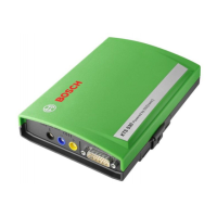
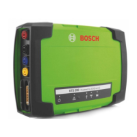
22 | KTS 530 / KTS 540 / KTS 570 | Initial start-up
3. I nitial start-up
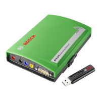
Do not plug in the Bluetooth USB adapter until
req ues ted to do s o during ins tallation of the Blue-
tooth driv er on y our P C or laptop (Message: Connect
Bluetooth device).
If the Bluetooth USB adapter is plugged in too soon, the
Windows hardware assistant is opened. The Windows
hardware assistant must be terminated and the Blue-
tooth USB adapter removed.
3.1 Assembly mount
The mount included with the delivery allows fastening
and loosening the KTS modules on the Bosch trolley
(possible as of production date 03-2006 only).
Screw in the three fillister head screws on the Bosch
trolley (see Fig. 4).
Fig. 4 A ssembly mount
Using the sheet-metal screws included with the de-
livery, screw the mount onto the KTSmodule (holes
for mounting are on the rear of the module).
Correct the screw penetration of the fillister head
screws on the vehicle so that the KTSmodules are
solidly and securely seated in position following instal-
lation.
3.2 ESI[ tronic] software installation
ESI[tronic] 2006/3 U* (with blue U*).
Depending on the type of installation selected, you
will be asked to insert ESI[tronic] 2006/1 during the
installation.
1.
2.
3.
1.
0
If the ESI[tronic] has not been enabled yet, enable it now.
How to install and enable the ESI[tronic] is described
on the "ESI[tronic] DVD 1 Diagnosis and technology"
in the directory 'DOCS\ SETUP\ IN F O _X X X .PD F '.
3 .3 C o n n e c tio n
C o n n e c t th e K T S m o d u le w ith th e p o w e r s u p p ly
in c lu d e d w ith th e d e liv e r y .
C o n n e c t th e K T S m o d u le w ith th e P C / L a p to p u s in g
th e U S B c o n n e c tio n c a b le .
T h e m e s s a g e "F o u n d n e w h a rd w a re " w ill a p p e a r
o n th e s c re e n th e firs t tim e th a t th e K T S m o d u le s
a re c o n n e c te d u s in g th e U S B c o n n e c tio n c a b le .
T h is in d ic a te s th a t th e U S B c o n n e c tio n to th e
K T S m o d u le s h a s b e e n re c o g n iz e d .
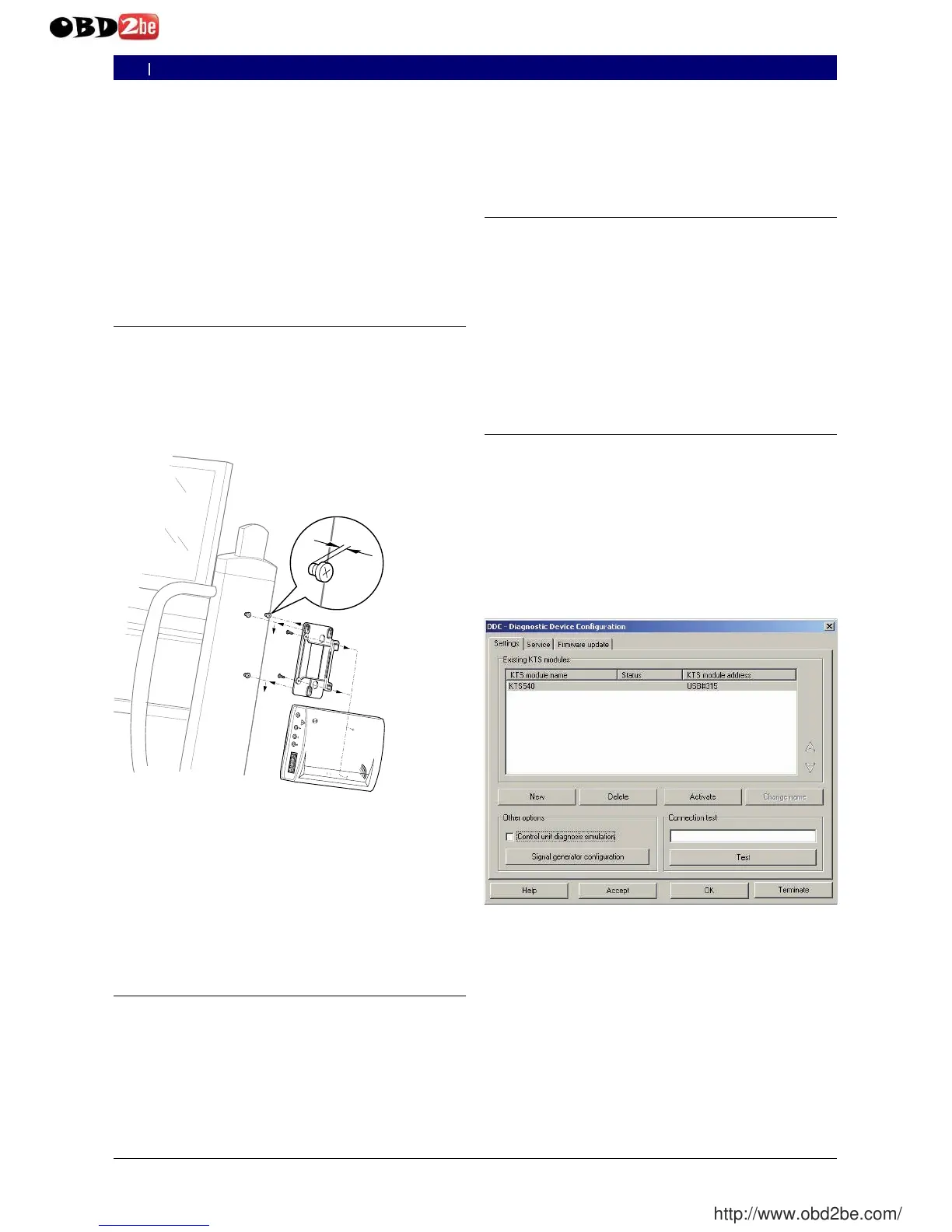
3 .4 C o n fig u r a tio n ( D D C )
T h e fu n c tio n o f th e D D C ( D ia g n o s tic D e v ic e C o n fig u -
ra tio n ) s o ftw a re is to c o n fig u re , a c tiv a te a n d te s t th e
K T S m o d u le s .
S ta r t th e D D C ( " Start >> Settings >> Control
p anel") .
C o n firm th e D D C fa u lt m e s s a g e w ith <O K > .
A lw a y s re m o v e th e s a m p le e n tr y "K T S 5 4 0 ".
A d d th e K T S m o d u le v ia "N ew ".
O th e r p ro c e d u re s fo r c o n fig u ra tio n c o n c e rn in g th e
in itia l s ta r t-u p a re d e s c rib e d in th e o n lin e h e lp . U s e
<H e lp > to o p e n th e o n lin e h e lp . A ll o th e r im p o r ta n t
in fo rm a tio n c o n c e rn in g D D C is fo u n d h e re a s w e ll.
If y o u h a v e a n y q u e s tio n s w h ic h c a n n o t b e a n s w e re d
b y th e o n lin e H e lp , p le a s e c o n ta c t th e E S I[ tro n ic ]
s e r v ic e h o tlin e d ire c tly .
2.
0
1 .
2.
0
0
1 .
2.
3 .
4 .
0
0
e n
 Loading...