English – 2
Product description and
specifications
Intended use
The drive unit is intended exclusively for driving your eBike
and must not be used for any other purpose.
In addition to the functions shown here, changes to software
relating to troubleshooting and functional modifications may
be introduced at any time.
Product features
Individual illustrations in these operating instructions may
differ slightly from the actual conditions depending on the
equipment of your eBike.
The numbering of the components shown refers to the illus-
trations on the graphics pages at the beginning of the
manual.
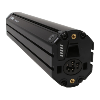
(1)
Drive unit
(2)
Speed sensor
(3)
Speed sensor spoke magnet
(4)
Speedsensor (slim)
A)
(5)
Magnet
B)
A) different sensor type and installation position is possible
B) different installation position is possible
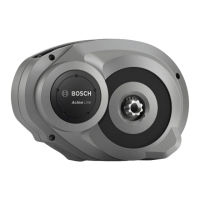
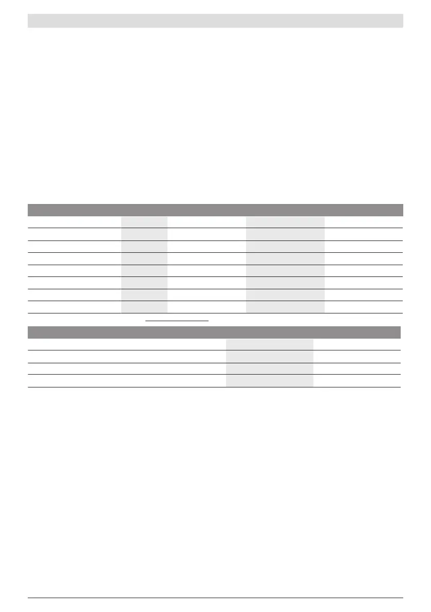
Technical data
Drive unit ActiveLine ActiveLinePlus PerformanceLine
Product code BDU310 BDU350 BDU365
Continuous rated power W 250 250 250
Torque at drive, max. Nm 40 50 65
Rated voltage V= 36 36 36
Operating temperature °C –5to+40 –5to+40 –5to+40
Storage temperature °C +10to+40 +10to+40 +10to+40
Protection rating IP54 IP54 IP54
Weight, approx. kg 2.9 3.2 3.2
The Bosch eBike system uses FreeRTOS (seehttp://www.freertos.org).
Bicycle lights
A)
Voltage approx.
B)
V= 12
Maximum power
– Front light W 17.4
– Tail light W 0.6
A) Depends on legal regulations, not possible in all country-specific models via the eBike battery
B) When changing the bulbs, ensure that they are compatible with the Bosch eBike system (ask your bicycle dealer) and are suitable for the
specified voltage. Bulbs must only be replaced with bulbs of the same voltage.
Inserting a bulb incorrectly can cause it to blow.
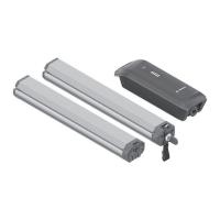
Assembly
Inserting and removing the battery
For inserting and removing the eBike battery in/from the
eBike, please read and observe the battery operating in-
structions.
Checking the speed sensor (see figure A)
Speedsensor (standard)
The speed sensor (2) and its spoke magnet (3) must be fit-
ted such that the spoke magnet moves past the speed
sensor at a distance of at least 5 mm and at most 17 mm
with each rotation of the wheel.
Note: If the distance between the speed sensor (2) and the
spoke magnet (3) is too small or too large, or if the speed
sensor (2) is not properly connected, the speedometer dis-
play will fail and the eBike drive unit will operate in emer-
gency mode.
Should this occur, loosen the screw of the spoke magnet (3)
and fasten the spoke magnet to the spoke such that it runs
past the marking on the speed sensor at the correct clear-
ance. If the speed is still not being indicated on the speedo-
meter display after doing this, please contact an authorised
bicycle dealer.
Speedsensor (slim)
The speedsensor (slim)(4) and its magnet(5) must be
mounted in such a manner that the magnet, after a turn of
the wheel, moves past the speed sensor with a clearance of
at least 2 mm, yet no more than 8 mm.
0 275 007 XD3 | (19.03.2020) Bosch eBike Systems
 Loading...