EasyManua.ls Logo

Bosch WORCESTER GREENSTAR User Manual

Bosch WORCESTER GREENSTAR
20 pages
To Next Page IconTo Next Page
To Previous Page IconTo Previous Page
Page #10 background imageLoading...
Page #10 background image
Installation
GREENSTAR WIRING CENTRE – 6720880441 (2018/01)
10
3.3 Connection diagrams with system schematics
The circuit diagrams are only schematic illustrations and provide a non-
binding indication of possible installations. Install safety equipment in
accordance with applicable standards and local regulations. For further
information refer to the installation instructions of the boiler and control
accessory selected or for the the additional system components (not
supplied by Worcester, Bosch Group) those supplied by the
manufacturer.
The Worcester, Bosch Group customer service may be contacted on the
telephone number on the back of these instructions.
When using any other controls other than Worcester Comfort controls,
install the jumper supplied with the Greenstar Wiring Centre which can
be found in the bag with the installation materials.
To ensure an economical and comfortable DHW temperature and
sufficient protection against bacterial contamination in the DHW
cylinder, temperature switch II should be set to at least 60 °C. To
reduce the risk of scalding, temperature switch II should be set below
60 °C.
Installation of room thermostat or link wire
The Greenstar Wiring Centre is compatible with the following Worcester
plug-in wireless programmable devices and room temperature-
dependent controllers:
7733 600 001; Comfort I RF twin-channel timer and room
thermostat
7733 600 002; Comfort II RF programmable room thermostat and
receiver
When using any other controls other than Worcester controls, install
the jumper supplied with the Greenstar Wiring Centre which can be
found in the bag with the installation materials ( Fig. 1, page 4),
connect terminals IZ3 – L and IZ3 – IN.
Fig. 20 Connection using the jumper supplied with the Greenstar
Wiring Centre
230 V AC Mains voltage
Earth lead
L Phase (mains voltage)
N Neutral conductor
I Code switch I – system type
II Temperature switch II – domestic hot water cylinder
temperature
BUS BUS EMS 2
Protection of unvented domestic hot water cylinders
NOTICE:
Greenstar Wiring Centre fault isolation!
Never take the feed to the safety limit thermostat through the control
thermostat. The cylinder will never reach the temperature set using
temperature switch II if the control thermostat is set at a lower
temperature.
The Greenstar Wiring Centre must be wired as follows when installed in
combination with an unvented domestic hot water cylinder:
Fig. 21 Connection of power supply for installation in combination with
an unvented domestic hot water cylinder
1 Fused spur
2 Greenstar Wiring Centre
3 Unvented domestic hot water cylinder's dual thermostat
4 Dual thermostat's control thermostat (must not be used)
5 Dual thermostats high limit thermostat
Earth lead
L Phase (230 V AC)
N Neutral conductor
The installation will use the cylinder temperature sensor (Greenstar)
supplied with the TC1 Wiring Centre.
The installation therefore does not need to use the hot water control
thermostat of the cylinder's dual thermostat.
The installation may require altered wiring of the dual thermostat
(depending on the cylinder and thermostat manufacturer) to
exclusively use the safety thermostat of the dual thermostat.
The safety thermostat section of the dual thermostat must be wired
in such a way as to interrupt the permanent live connection to the
Greenstar Wiring Centre ( Fig. 21).
The two-port valve supplied with the unvented cylinder must be
installed and connected correctly ( Fig. 25, page 14).
0
1
2
3
4
S
Y
I
off
off
40
40
50
50
60
60
70
70
max
max
II
II
230 V AC 230 V AC
L
N
L
N
BUS
0 010 017 134-001
1212 12
TC1 T0
BUS
BUS
12
BUS
123 1
OS1
212
MD1
12
T1
24 V
NL N LNINLINLINLINL
120/230VAC 120/230VAC
IZ1 IZ2 IZ3 IZ4
120/230 V AC
N N 43 N 1414
PZ2 PZ3PZ1
120/230 V AC
12
BUS
NL
120/230VAC
. . . . .
L
N
0 010 017 138-001
2 3
45
1
Question and Answer IconNeed help?

Do you have a question about the Bosch WORCESTER GREENSTAR and is the answer not in the manual?

Bosch WORCESTER GREENSTAR Specifications

General IconGeneral
BrandBosch
ModelWORCESTER GREENSTAR
CategoryIndustrial Equipment
LanguageEnglish

Summary

1 Explanation of symbols and safety instructions

1.1 Explanation of symbols

Defines signal words used for warnings and their meanings.

1.2 General safety instructions

Provides essential safety notices for installation contractors and users.

2 Product Information

Intended use

Describes the module's intended communication via EMS 2 interface.

Installation, commissioning and maintenance

States that installation must be done by a competent person and to use genuine spare parts.

Electrical work

Emphasizes electrical work must be done by a qualified electrician and outlines safety precautions.

Handover to the user

Instructs on explaining system operation, safety, and maintenance to the user.

Damage caused by frost

Advises on preventing frost damage and keeping the system operational.

2.1 Important notices on use

Highlights risks like scalding and floor damage with specific warnings.

2.2 Scope of delivery

Specifications

Details the product's technical specifications, including dimensions and ratings.

2.4 Cleaning and care

Provides instructions on how to clean the module casing.

2.5 Additional accessories

Installation of additional accessories

Guides on fitting accessories according to regulations and supplied instructions.

3 Installation

3.1 Installation

Describes the process of mounting the module on a wall or mounting rail.

DANGER: Danger to life due to current!

Critical safety warning about electric shock hazards during installation.

3.2 Electrical connection

DANGER: Danger to life due to current!

Reinforces the critical danger of electric shock from live parts.

3.2.1 Connecting the BUS connection and temperature sensor (extra-low voltage side)

Details connecting the BUS and temperature sensor, including cable length and interference avoidance.

3.2.2 Mains voltage, pump and valve connection (mains voltage side)

DANGER: Danger to life due to current!

Crucial warning about the risk of electric shock from mains voltage.

Electrical connection – Step 1

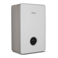
First step in electrical connection: routing cables through grommets and connecting to plugs.

Electrical connection – Step 2

Second step in electrical connection: re-inserting grommets and plugging in connected cables.

Electrical connection – Step 3

Electrical connection – Step 4

Fourth step: re-inserting grommet and plugging in connected plugs.

Electrical connection – Step 5

Fifth step: securing connected cables with strain relief.

Electrical connection – Step 6

Sixth step: routing cables, removing plugs, connecting, and re-routing.

Electrical connection – Step 7

Electrical connection – Step 8

Eighth step: replacing grommets and plugging in connected plugs.

Fitting the cover – Step 9

Final step: fitting the module cover after connections are made.

3.3 Connection diagrams with system schematics

Protection of unvented domestic hot water cylinders

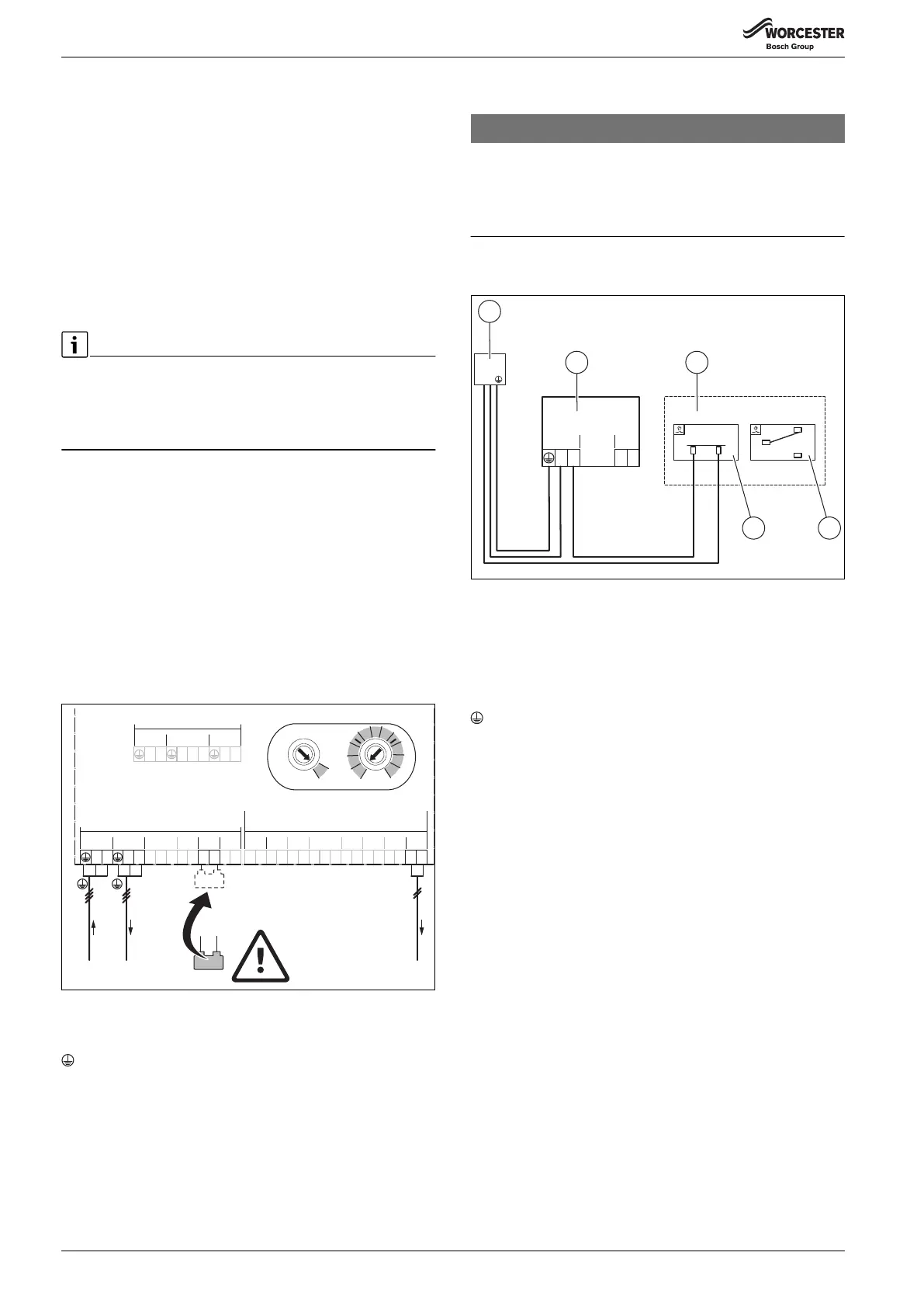
Guidance on wiring for unvented DHW cylinders, including safety limit thermostat interaction.

NOTICE: Greenstar Wiring Centre fault isolation!

Warning against taking feed through control thermostat to safety limit thermostat.

Installation of room thermostat or link wire

Details on connecting room thermostats or link wires, including jumper use.

3-way valve (Y-plan) system

System components:

Lists components and their connections for the Y-plan system.

Terminal identification:

Defines the terminals on the module and their functions for the Y-plan system.

Two-port valve (S-plan) system

System components:

Lists components and their connections for the S-plan system.

Terminal identification:

Defines module terminals and their functions for the S-plan system.

3 heating circuits without electronic mixing valves

System components:

Lists components and their connections for 3 heating circuits.

Terminal identification:

Defines module terminals and their functions for 3 heating circuits.

*) The marked system components are connected...

Notes on connecting system components with coding 3 for 3 heating circuits.

2 heating circuits without electronic mixing valves and one domestic hot water cylinder circuit (S-plan Plus), with 2x Comfort II RF programmable room thermostats for load compensation

Worcester products required:

Lists the necessary Worcester products for this system configuration.

Unvented DHW cylinder G3 compliance

Ensures G3 compliance for unvented DHW cylinders via safety thermostat power supply.

Commissioning the Greenstar Wiring Centre

Details the dial settings and hot water temperature adjustment for commissioning.

Commissioning the Comfort II RF

Explains pairing and setup for Comfort II RF thermostats for zone 1 and zone 2.

3.5 Using the system

During a simultaneous central heating and hot water demand...

Explains priority given to hot water and valve motorisation times.

3.6 Step-by-step pairing instructions for Comfort II RF

Pairing

Step-by-step guide to pairing Comfort II RF devices with the receiver.

Unpairing

Step-by-step guide to unpairing Comfort II RF devices from the receiver.

Commissioning

General commissioning steps: electrical connections, power supply, and system setup.

Troubleshooting

Code switch I

Explains how Code Switch I sets the system type (Y-plan, S-plan, etc.).

Temperature switch II

Details the function of Temperature Switch II for DHW temperature and legionella protection.

System and module commissioning

Outlines the steps for system and module commissioning, including code switches and power-on.

5.1 Status indicator

Describes the module's status indicator and its possible causes and remedies.

5.2 Replacing the fuse

Provides safety instructions and steps for replacing the module's fuse.

DANGER: Danger to life due to current!

Critical safety warning about electric shock when handling the fuse.

6 Environmental protection/disposal

Packaging

Describes the company's commitment to country-specific recycling for packaging materials.

Old electrical and electronic appliances

Guides on the environmentally compatible recycling of old electrical and electronic appliances.

Related product manuals