Installation
GREENSTAR WIRING CENTRE – 6720880441 (2018/01)
6
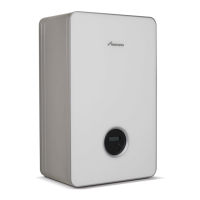
Mounting rail installation
▶ Mount the module on a mounting rail.
Fig. 7 Mounting rail installation
▶ Unmount the module from the mounting rail.
Fig. 8 Disassembly from mounting rail
3.2 Electrical connection
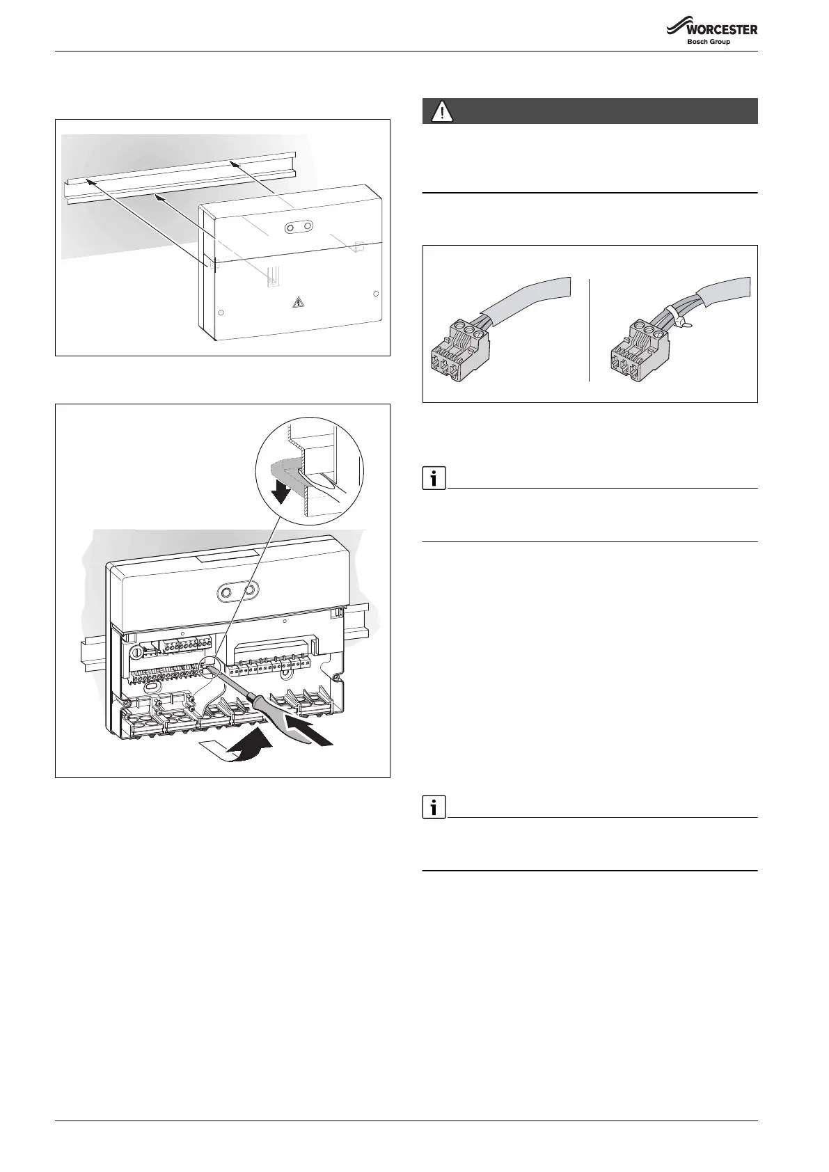
DANGER:
Danger to life due to current!
▶ Secure the wires of all connected cables together. This can only be
carried out by stripping back a short section of cable sheath or by
using cable ties close to the terminals ( Fig. 9).
▶ Observe current regulations applicable to power connections, and
use at least cable type H05 VV-…
Fig. 9 Secure the wires of all connected cables
3.2.1 Connecting the BUS connection and temperature sensor
(extra-low voltage side)
If the maximum cable length of the BUS connections between all BUS
nodes is exceeded, or if the BUS system has a ring structure, the system
cannot be commissioned.
Maximum total length of BUS connections:
• 100 m with 0.50 mm
2
conductor cross-section
• 300 m with 1.50 mm
2
conductor cross-section
▶ To avoid inductive interference: make sure all low-voltage cables are
routed separately to mains voltage cables (min. clearance 100 mm).
▶ In the case of external inductive interferences (e.g. from PV
systems), use shielded cables (e.g. LIYCY) and earth the shield on
one side. The shield should be connected to the building's earth lead,
e.g. to a free earth conductor terminal or water pipe, and not to the
terminal for the earth lead in the module.
▶ Connect 1 pair of BUS terminals (BUS 1 and BUS 2) to the BUS
terminals of the boiler.
▶ Connect the cylinder temperature sensor supplied to the terminal
TC1.
For hot water cylinders without sensor pockets, use the cylinder sensor
retaining device to mount the cylinder temperature sensor securely to
the side of the cylinder.
When sensor leads are extended, use the following conductor cross-
sections:
• Up to 20 m with 0.75 mm
2
to 1.50 mm
2
conductor cross-section
• 20 m to 100 m with 1.50 mm
2
conductor cross-section
▶ Route cables through the grommets provided and connect them as
described in chapter 3.3.
0 010 013 188-001
0 010 013 189-001
2.
3.
1.
0010016333-001

 Loading...