Installation
GREENSTAR WIRING CENTRE – 6720880441 (2018/01)
5
2.5 Additional accessories
For precise information regarding suitable accessories, refer to the
catalogue.
• For a 3-way valve (Y-plan) system:
– Circulating pump; connection to PZ3
– Y-plan diverter valve; connection to PZ1 and PZ2
– Room and/or frost stats (optional); connection to IZ3 and IZ4
• For a two-port valve (S-plan) system:
– Circulating pump; connection to PZ3
– 2 x two-port valves (with limit switches); connection to PZ1 and
IZ1 and to PZ2 and IZ2
– Room and/or frost stat (optional); connection to IZ3 and IZ4
• For heating circuits with separate heating pumps without electronic
mixing valves (e.g. downstream of low-loss header):
– Circulating pump; connection to PZ1...3
– Room thermostat (optional); connection to IZ1...3
• For a cylinder charging circuit with separate cylinder primary pump
(e.g. downstream of low-loss header):
– Cylinder primary pump; connection to PZ1
– Cylinder temperature sensor; connection to TC1
Installation of additional accessories
▶ Fit additional accessories according to legal requirements and the
installation instructions supplied.
▶ The Greenstar Wiring Centre is compatible with the following
Worcester plug-in wireless programmable devices and room
temperature-dependent controllers:
– 7733 600 001; Comfort I RF twin-channel timer and room
thermostat
– 7733 600 002; Comfort II RF programmable room thermostat
and receiver
3 Installation
DANGER:
Danger to life due to current!
Touching live parts can result in an electric shock.
▶ Before installing this product: Disconnect the heat source and all
other BUS nodes from the mains voltage across all poles.
▶ Before commissioning: fit the cover ( Fig. 19, page 9).
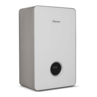
3.1 Installation
Wall installation
▶ Mount the module on a wall.
Fig. 4 Wall installation – Step 1
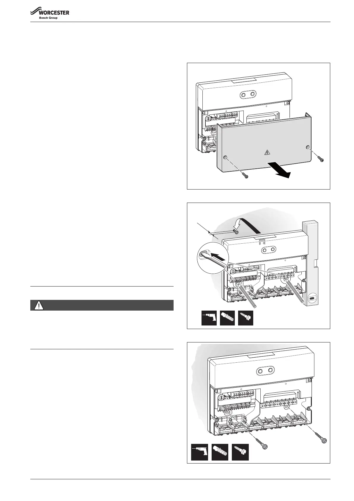
Fig. 5 Wall installation – Step 2
Fig. 6 Wall installation – Step 3
0 010 013 184-001
6 mm 3,5 mm6 mm
3.
2.*
*
~ 1,5 mm
4.
0 010 013 185-001
1.
4.
4.
0 010 013 186-001
6 mm 3,5 mm6 mm

 Loading...