33
DISASSEMBLY PROCEDURES
Note: Refer to the photos at right for the
following procedures.
CAUTION: Be sure AC mains power is
removed before disassembling the unit.
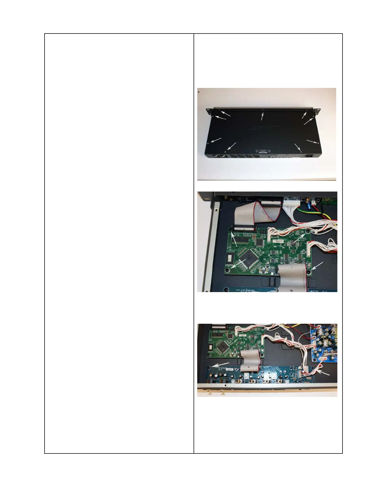
1. Top Cover Removal
1.1 Remove the nine screws as shown at
right. Lift up the back edge of the top cover
and slide it off the chassis.
2. DSP PCB Removal
2.1 Perform procedure 1.
2.2 Unplug the wire harnesses at connectors
CN500, CN502 and CON500.
2.3 Locate the wire harness that connects to
CN501. Unplug the wire harness from the
switch-mode power supply PCB (13) at XS4.
2.4 Remove the four screws that secure the
DSP PCB to the chassis.
2.5 Lift out the DSP PCB.
3. Input / Output PCB Removal
3.1 Perform procedure 1.
3.2 Unplug the ribbon cable at J705. Unplug
the wire harness at J202. Unplug the wire
harness at J707.
3.3 Locate the wire harness at J706. Follow
the wire harness to the switch-mode power
supply PCB and unplug it from the connector
at XS5.
 Loading...