4 • English PowerSpace P2600A/P21000A/P4300A • Installation Guide
PRO.BOSE.COM
Product Details
PowerSpace P2600A/P21000A
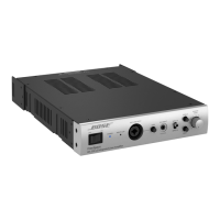
Front Panel
PowerSpace Versatile Power Amplifier
1
POWER
SIGNAL
LIMIT
2
P2600A
q Power switch:
In/Out standby mode.
w Power LED:
Power or fault state
indication.
White (solid): Power is on
White (blinking): Unit is in standby mode
Red (solid): Power supply fault
Red (blinking): Thermal fault
e Input Signal LED:
Each LED operates
independently.
Green: Signal present
Amber: Input is near clipping
Red: Input is clipping
r Output Limit LED:
Each LED operates
independently.
Amber: Amplifier limiting an output
Red (both solid): Amplifier fault
Red (blinking): Outputs are muted
q w e r
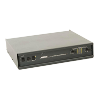
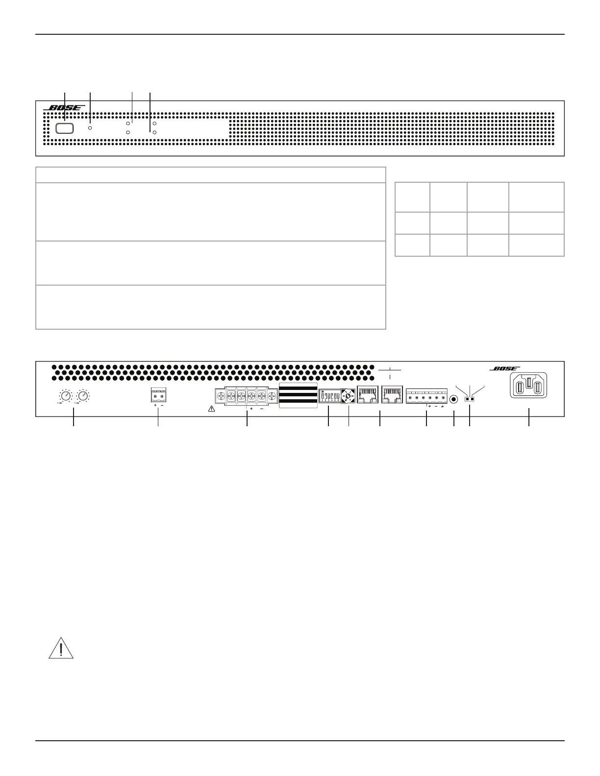
Rear Panel
100-240V ~ 50/60HZ
570W MAX
PowerSpace P2600A
Versatile Power Amplifier
2
0
1
0
OUTPUT ATTENUAT ION MUTE OUTPUT
12
CLASS 2
WIRING
SWITCH SETTINGS OFF ON
1 AUTO STANDBY OFF ON
2 MUTE POLARITY NO NC
3 GLOBAL OUT 70V 100V
4 OUTPUT 1 HiZ LowZ
5 OUTPUT 2 HiZ LowZ
6 I-SHARE OFF ON
OUTPUTS
INPUT
SELECT
4. 5–6
5. 7–8
Analog Input
0. 1:1
1. 1:ALL
2. 1–2
3. 3–4
AmpLink Input
AmpLink
INPUT THRU
INPUT
12
UPDATE
GAIN
(SENSITIVITY)
HIGH MID LOW
(-10 dBV) (4 dBu) (14 dBu)
ERRLNK ERRLNK
q Output Attenuation controls: Output attenuation controls for each output. Turn the controls clockwise to decrease attenuation and
counter-clockwise to increase attenuation. The attenuator must be at 0 dB attenuation for the respective output to reach rated power.
w Mute: Normally open or normally closed dry contacts can mute all outputs. Mute polarity can be inverted by a DIP switch.
e Output terminal block: 4-terminal block connector for loudspeaker connections. Each channel can deliver up to 600 watts (P2600A) or
up to 1000 watts (P21000A) regardless of load into 4, 8, 70V, or 100V. Outputs can be I-Shared.
r DIP switches: A bank of switches used to set amplifier configuration.
1. Auto Standby: If enabled (On), the amplifier goes into lower-power mode after 20 minutes without an input signal. If in lower-
power mode and an audio signal is detected, the amplifier will automatically wake and amplify audio within one second. The default
position is O.
2. Mute Polarity: Switch mute polarity between NO (normally open) or NC (normally closed). NO is the default position.
3. Global Out: Sets the output capability to 70V or 100V for all outputs that have their DIP switch set to Hi-Z. In 70V Hi-Z mode and
Low-Z mode, 100 V
P
and 70 V
RMS
limiters are automatically loaded. In 100V Hi-Z mode, 100 V
RMS
limiters are automatically loaded.
4. Output 1: Select 70/100V high-impedance output (Hi-Z) or 4–8 low-impedance output (Low-Z) for Output 1.
5. Output 2: Select 70/100V high-impedance output (Hi-Z) or 4–8 low-impedance output (Low-Z) for Output 2.
6. I-Share 1 & 2: Deliver 2× channel power by combining the current of Outputs 1 & 2. While the amplifier is o or in Standby mode,
set this DIP switch to On and install the included jumper across the four-output terminals. Then wire the loudspeaker load to the
amplifier using terminals 1+ and 1– (or 2+ and 2–).
t Input Select control: Dial selects if analog or AmpLink audio inputs are used. The default state is analog 1:1.
y AmpLink ports: Input RJ-45 connector that receives up to eight digital channels from a Bose AmpLink product. The amp also supports
a Thru path for daisy-chaining all eight digital audio channels to up to eight other Bose AmpLink products, at a maximum distance of
10 meters between products.
CAUTION: Shielded EIA/TIA 568B straight Cat 5 cable, or equivalent, is required for proper AmpLink operation. Unshielded
cable is not supported and may cause AmpLink audio to operate improperly. Do NOT connect either RJ-45 port to an Ethernet-
based network.
u Analog Input: Line-level input for balanced analog audio signals.
i Update port: Used for firmware updates.
o Gain/Sensitivity switch: Slide switch to set global gain/sensitivity setting to high gain (–10 dBv sensitivity), mid gain (4 dBu sensitivity),
or low gain (14 dBu sensitivity).
a Power input: Power cord connection (IEC 60320-C14 inlet). Removing the power cord when the amplifier is on is an acceptable power-
down method.
q w e r t y u i o a
Faults Only
Power
Supply
Fault*
Thermal
Fault
Amplifier
Fault
Power
LED
Solid
red
Blinking
red
—
Limit
LEDs
— All solid
red
All solid red
*Except for AC loss
If a power supply or amplifier fault cannot
be cleared, then the amplifier needs to be
replaced.
 Loading...