English • 5Installation Guide • PowerSpace P2600A/P21000A/P4300A
PRO.BOSE.COM
Product Details
PowerSpace P4300A
Front Panel
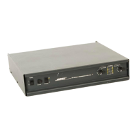
PowerSpace Versatile Power Amplifier
1
POWER
SIGNAL
LIMIT
2
3 4
P4300A
q Power switch:
In/Out standby mode.
w Power LED:
Power or fault state
indication.
White (solid): Power is on
White (blinking): Unit is in standby mode
Red (solid): Power supply fault
Red (blinking): Thermal fault
e Input Signal LED:
Each LED operates
independently.
Green: Signal present
Amber: Input is near clipping
Red: Input is clipping
r Output Limit LED:
Each LED operates
independently.
Amber: Amplifier limiting an output
Red (solid): Ch 1 & Ch 2 amplifier A fault
Ch 3 & Ch 4 amplifier B fault
Red (all solid): Thermal fault
Red (blinking): Outputs are muted
q w e r
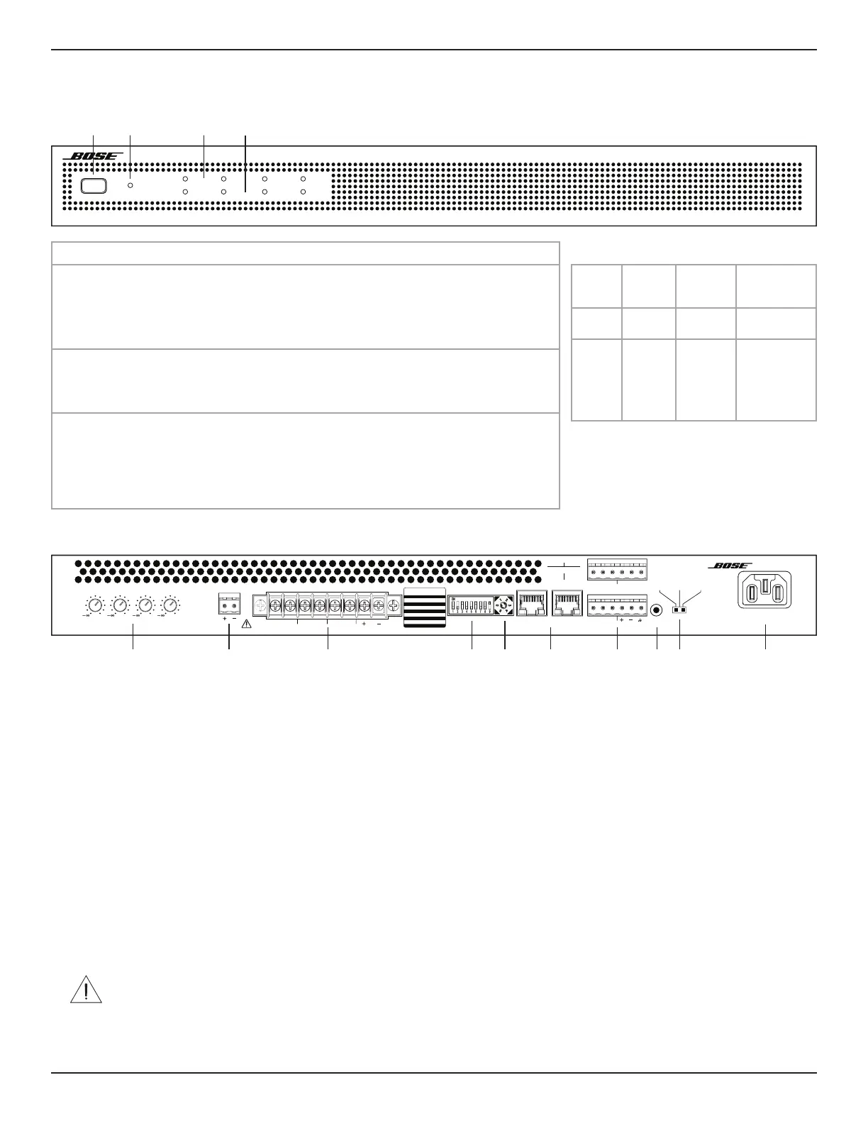
Rear Panel
100-240V ~ 50/60HZ
950W MAX
PowerSpace P4300A
Versatile Power Amplifier
2
0
1
0
4
0
3
0
OUTPUT ATTENUAT ION MUTE OUTPUT
CLASS 2
WIRING
INPUT
SELECT
AmpLink
INPUT THRU
INPUT
UPDATE
GAIN
(SENSITIVITY)
HIGH MID LOW
(-10 dBV) (4 dBu) (14 dBu)
ERRLNK ERRLNK
12
3412
SWITCH
SETTINGS OFF ON
1 AUTO STDBY OFF ON
2 MUTE NO NC
3 GLOBAL OUT 70V 100V
4 OUTPUT 1 HiZ LowZ
5 OUTPUT 2 HiZ LowZ
6 OUTPUT 3 HiZ LowZ
7 OUTPUT 4 HiZ LowZ
8 I-SHARE 1 & 2 OFF ON
9 I-SHARE 3 & 4 OFF ON
4. —
5. —
Analog Input
0. 1:1
1. 1:ALL
2. 1–4
3. 5–8
AmpLink Input
34
q Output Attenuation controls: Output attenuation controls for each output. Turn the controls clockwise to decrease attenuation and counter-
clockwise to increase attenuation. The attenuator must be at 0 dB attenuation for the respective output to reach rated power.
w Mute: Normally open or normally closed dry contacts can mute all outputs. Mute polarity can be inverted by a DIP switch.
e Output terminal block: 8-terminal block connector for loudspeaker connections. Each channel can deliver up to 300 watts regardless of load
into 4, 8, 70V, or 100V. Each output pair can be I-Shared.
r DIP switches: A bank of switches used to set amplifier configuration.
1. Auto Standby: If enabled (On), the amplifier goes into lower-power mode after 20 minutes without an input signal. If in lower-power mode
and an audio signal is detected, the amplifier will automatically wake and amplify audio within one second. The default position is O.
2. Mute Polarity: Switch mute polarity between NO (normally open) and NC (normally closed). NO is the default position.
3. Global Out: Sets the output capability to 70V or 100V for all outputs that have their DIP switch set to Hi-Z. In 70V Hi-Z mode and Low-Z
mode, 100 V
P
and 70 V
RMS
limiters are automatically loaded. In 100V Hi-Z mode, 100 V
RMS
limiters are automatically loaded.
4. Output 1: Select 70/100V high-impedance output (Hi-Z) or 4–8 low-impedance output (Low-Z) for Output 1.
5. Output 2: Select 70/100V high-impedance output (Hi-Z) or 4–8 low-impedance output (Low-Z) for Output 2.
6. Output 3: Select 70/100V high-impedance output (Hi-Z) or 4–8 low-impedance output (Low-Z) for Output 3.
7. Output 4: Select 70/100V high-impedance output (Hi-Z) or 4–8 low-impedance output (Low-Z) for Output 4.
8. I-Share 1 & 2: Deliver 2× channel power by combining the current of Outputs 1 & 2.
9. I-Share 3 & 4: Deliver 2× channel power by combining the current of Outputs 3 & 4.
Note: While the amplifier is o or in Standby mode, set one or both I-Share DIP switches to On and install the included jumper(s) across the first
four and/or last four terminals. Then wire the loudspeaker load(s) to the amplifier. Wire the I-Share 1 & 2 loudspeaker load to the amplifier using 1+
and 1– (or 2+ and 2–). Wire the I-Share 3 & 4 loudspeaker load to the amplifier using terminals 3+ and 3– (or 4+ and 4–).
t Input Select control: Dial selects if analog or AmpLink audio inputs are used. The default state is analog 1:1.
y AmpLink ports: Input RJ-45 connector that receives up to eight digital channels from a Bose AmpLink product. The amp also supports a Thru
path for daisy-chaining all eight digital audio channels to up to eight other Bose AmpLink products, at a maximum distance of 10 meters
between products.
CAUTION: Shielded EIA/TIA 568B straight Cat 5 cable, or equivalent, is required for proper AmpLink operation. Unshielded cable is not
supported and may cause AmpLink audio to operate improperly. Do not connect either RJ-45 port to an Ethernet-based network.
u Analog Input: Line-level input for balanced analog audio signals.
i Update port: Used for firmware updates.
o Gain/Sensitivity switch: Slide switch to set global gain/sensitivity setting to high gain (–10 dBv sensitivity), mid gain (4 dBu sensitivity), or low
gain (14 dBu sensitivity).
a Power input: Power cord connection (IEC 60320-C14 inlet). Removing the power cord when the amplifier is on is an acceptable power-down method.
q w e r t y u i o a
Faults Only
Power
Supply
Fault*
Thermal
Fault
Amplifier
Fault
Power
LED
Solid
red
Blinking
red
—
Limit
LEDs
— All solid
red
Ch 1 & 2
solid red,
Amplifier A
Ch 3 & 4
solid red,
Amplifier B
*Except for AC loss
If a power supply or amplifier fault cannot
be cleared, then the amplifier needs to be
replaced.
 Loading...