Page 19
Item Qty. Part No. Description
1 1 18189A Circuit Sentry Bkt. Assy.
includes:
2a 1 18180
• Decal, Installation Instructions
2b 1 18181
• Decal, 100 A Circuit Sentry Label
3 2 10377
• Rivet, Pop, 3/16" x 5/8"
* 2 11541 * Washer, #10 Flat
4 1 18178
• Circuit Breaker, 100 A
5 1 18138
• Bracket, Circuit Sentry
Item Qty. Part No. Description
6 4 10383 Screw, #8-18 x 1/2" Self-Tap
7 1 12764 Plastic, Flat,1/8" x 4" x 4"
8 1 13362A Lead Wire, #2 Ga. x 30"
9 1 13050 Spacer, 13/32" x 1/2"
10 1 10025 Bolt, 3/8"-16 x 1" Hex
11 1 13865 Terminal, 1/4" Eye
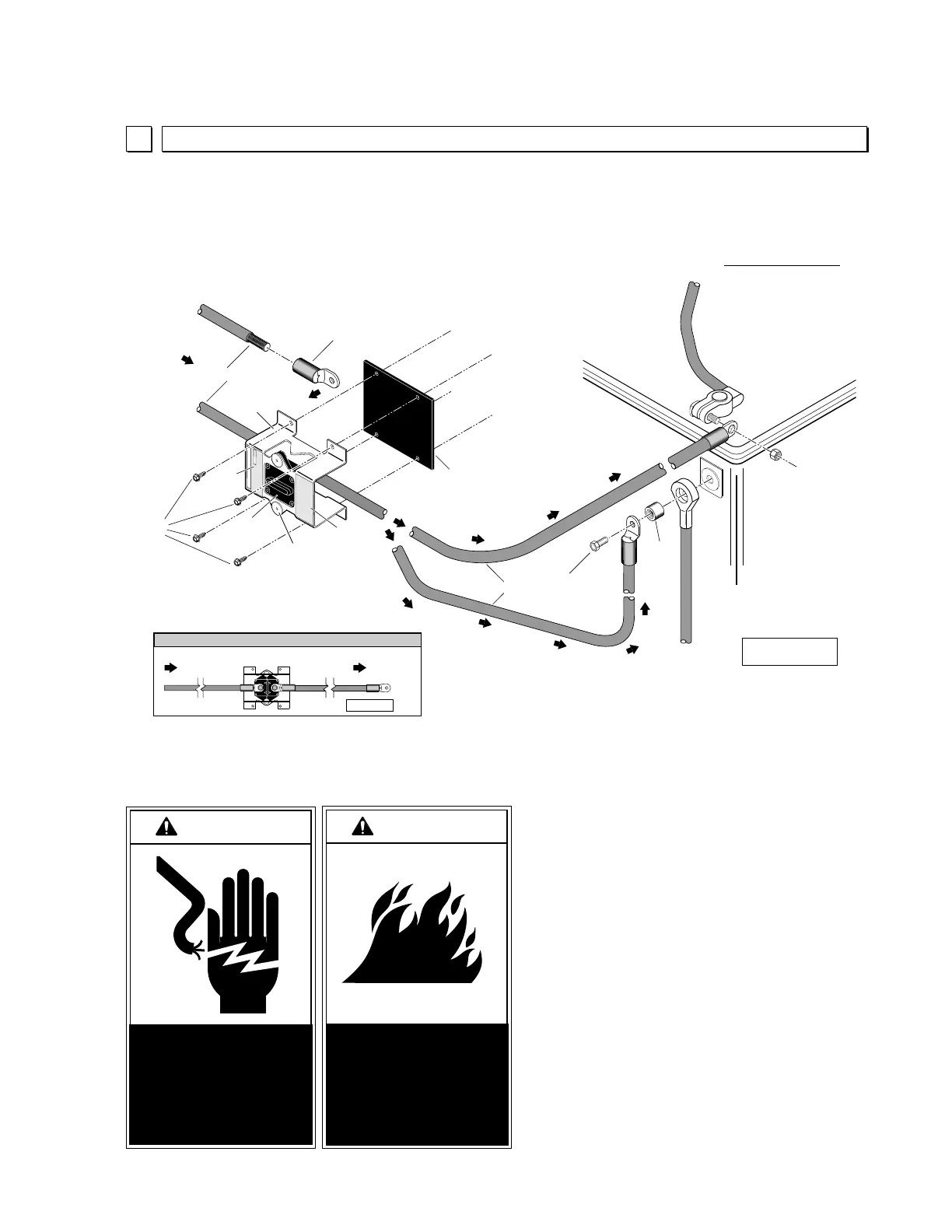
Figure P
* Indicates items not shown
Lift Installation Instructions
Attach the power cable to the Auxiliary
terminal of the circuit sentry as shown. Attach
one end of the 30" lead wire (item 8 above) to
the Battery circuit sentry terminal. Locate the
circuit sentry within 24" of the positive (+)
battery terminal and use self-tap screws to
fasten it to the fenderwell or other appropriate
mounting surface as shown. Important:
Sandwich the 1/8" x 4" x 4" plastic between
the circuit sentry and the mounting surface to
prevent electrical short circuits.
Note: A 3/8"-16 x 1" bolt and 13/32" I.D.
spacer are provided for side terminal mount
batteries. Install as shown.
Carefully connect the opposite end of the 30"
lead wire to the Positive (+) post of the
battery.
Use cable ties and/or 7/16" cable clips and
self-tap screws to secure the cable to the
underside of the vehicle (shown in Figure O).
4
Circuit Sentry Installation and Power Connection
W
A
RNING
W
A
RNING
Risk of electrical
shock! Use extra
care when making
electrical connec-
tions.
Risk of electrical fire!
Sandwich 1/8" plastic
between Circuit
Sentry and mounting
surface.
Note: Circuit Sentry #18190A is
supplied for 24 Volt Applications.
#13362A
Lead Wire
Connect to
(+) Battery Post
Lift
Power Cable
100 AMP
Circuit Sentry
6
4
3
5
Lift Power Cable
Lead Wire
11
7
10
8
9
Side
Post
Mount
Top Post
Mount
Positive (+)
12 Volt
Battery
Post
Circuit Sentry Termination
Back View
Lead wire (item 8)
Side Post Mount
Application
Lead wire (item 8)
Top Post Mount
Application
This unit is designed to protect the electrical system on
all Braun hydraulic wheelchair lifts. In the event of failure,
wait 60 seconds. Then turn RESET lever to reset breaker.
18181
Rating: 100 Amps
The Braun
Circuit Sentry
CAUTION!
Turn RESET lever to reset breaker only!
Turning lever at any other time will result in damage.
1. Attach lift power cable to
2. Attach battery lead cable to
3. Locate Circuit Sentry as specified in owner's/service
manual. Use self-tap screws to mount unit to
appropriate mounting surface. Sandwich flat
plastic between Circuit Sentry and mounting surface.
4. Attach battery lead cable to battery terminal.
auxiliary
battery
Installation Instructions
Note:
positive (+)
Circuit Sentry terminal.
Circuit Sentry terminal.
18180
Aux. Bat.
Route the lift power cable to Circuit Sentry installation location. Install terminal (item 11).
Connect terminal to Circuit Sentry terminal as shown in the Back View (below).
Auxiliary
2a
2b
H
I-A
M
P
W
ATERPROOF
184100P
B
u
s
s
1
0
0
A
 Loading...