21
1
2
Alternator Testing
The following alternator test procedures were
developed using the Fluke® Digital Multimeter.
When performing alternator tests with the
UNI-T® Digital Multimeter, refer to the operating
manual supplied with that meter for the proper
procedure.
All test values will be the same regardless the
meter used.
NOTE: Before testing alternator output, use an
accurate tachometer to temporarily adjust the
engine speed to the RPM specified in the test
instructions.
When testing alternators, perform the tests in the
following sequence:
1. Test alternator output.
2. Test diode(s) or regulator-rectifier (if
equipped).
The 0.5 Amp, DC alternator (Figure 2-6) is
designed to operate as an integral part of the
engine and is separate from the starting and
ignition system. It is intended to provide DC
charging current for a 12 Volt battery.
• Unregulated
• 0.5 Amps DC for charging battery
• One black lead (A) from stator
• White connector (B) output lead
Figure 2 - 6
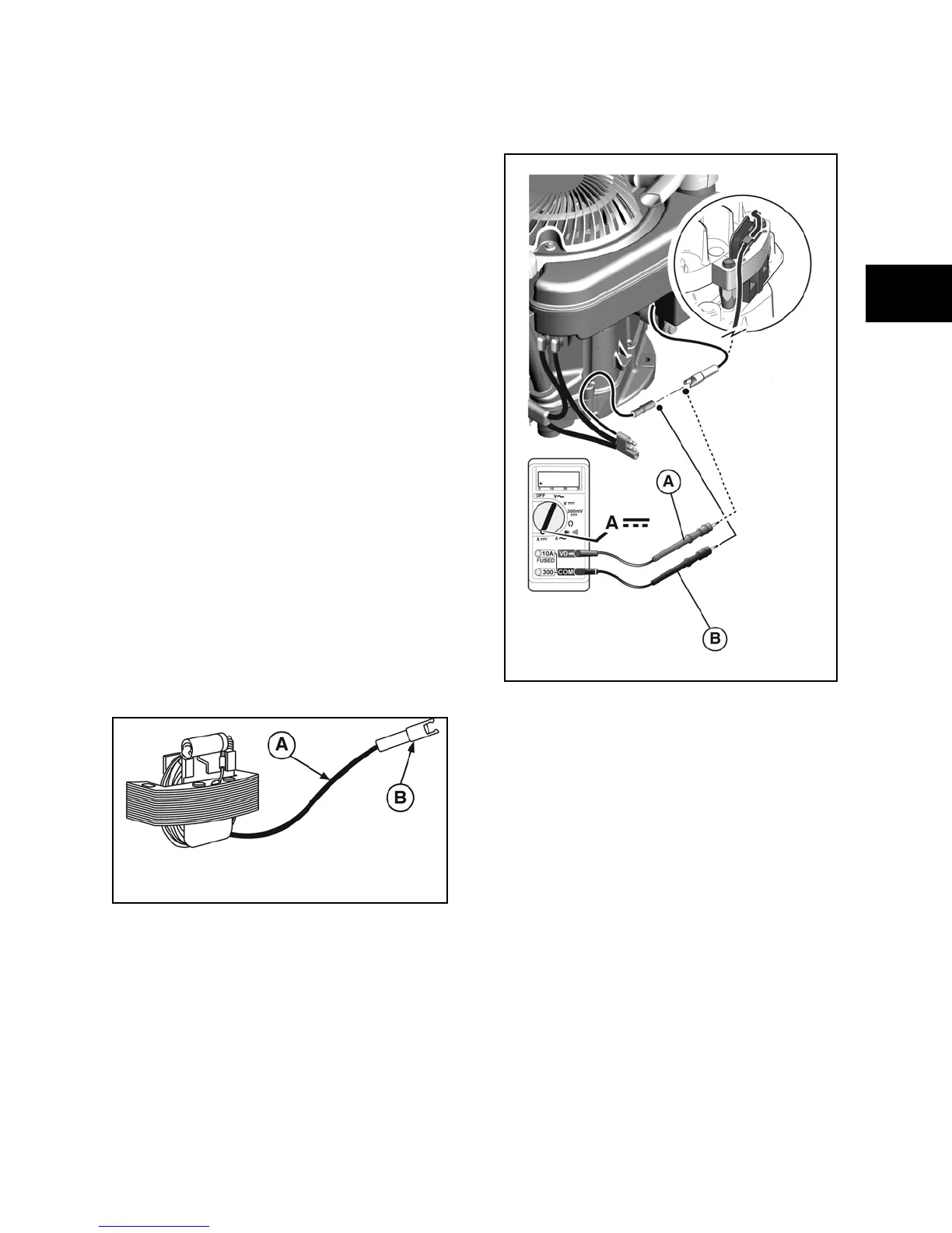
1. Disconnect charging lead to battery at
white connector.
2. Insert RED test lead into 10 Amp
receptacle in meter.
3. Insert BLACK test lead into COM
receptacle in meter.
4. Rotate selector to DC Amps position.
5. Attach RED test clip to output lead (A,
Figure 2-7).
6. Attach BLACK test clip to charging lead
(B).
Figure 2 - 7
7. Install tachometer, then start and run
engine at 2800 RPM. Meter should display
no less than 0.5 Amp DC.
8. If low or no output, check alternator air
gap. Adjust to value listed in Section 12 -
Engine Specifications.
9. If alternator air gap is within specification
and there is still low or no output, replace
alternator.
 Loading...