37
4
5
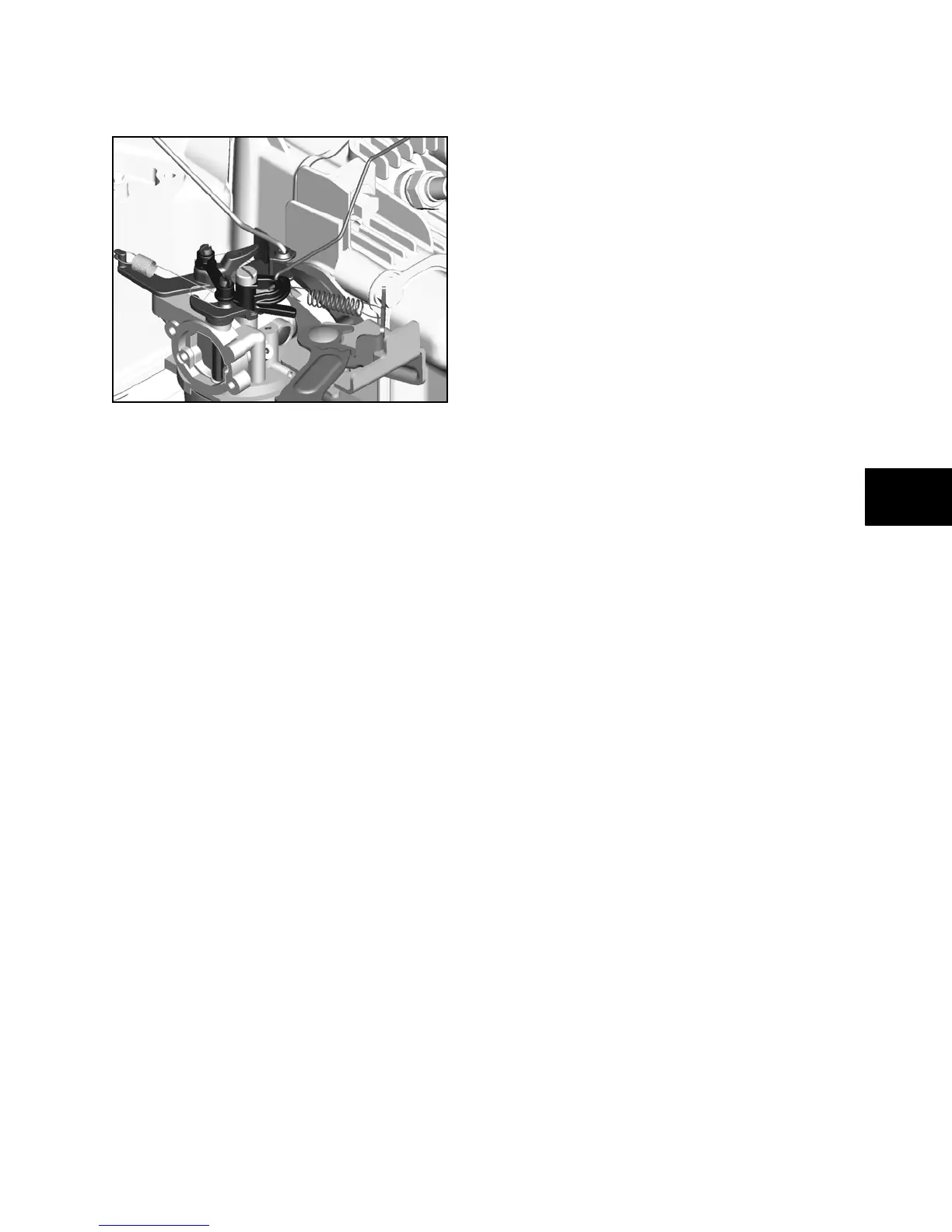
Linkage and Spring Orientation
Be sure to note orientation of linkages and
springs before removing (Figure 5-2).
Figure 5 - 2
Top No-Load RPM
Briggs & Stratton supplies engines with an
adjustable top no-load RPM, which the
equipment manufacturers set to their own
specifications. Do not exceed these limitations.
NOTE: Correct top-no-load RPM for each model-
type-trim can be found in the engine replacement
data on Briggs & Stratton websites.
Top no-load RPM should be checked with a
tachometer when the engine is operating on a
completely assembled unit. The equipment
should be operated under no-load when making
this check.
If a governor spring must be replaced, consult
the appropriate Illustrated Parts List for the
correct part number. After the spring is installed,
check the top no-load RPM with an accurate
tachometer, as noted above, and adjust as
required. (See Section 1 - Safety, Maintenance,
and Adjustments).
Governor Service
The mechanical governor is part of the oil slinger
assembly (A, Figure 5-1) attached to the sump.
The governor crank (B) is mounted in the
cylinder assembly.
Disassemble
1. Drain oil from engine into an appropriate
container.
2. Remove burrs and clean the crankshaft
PTO, the carefully remove sump from
engine and discard the gasket.
3. Loosen the governor lever nut and slide
the lever off the governor crank and
disconnect from the governor link. Set
aside.
4. Remove push nut or clip and washer (C)
from governor crank. Remove burrs and
clean the governor crank, then remove
crank from inside of cylinder.
NOTE: Inspect governor gear for worn weight
pins and chipped or missing gear teeth before
removing. Any time the governor gear is
removed, it must be discarded and replaced with
a brand new governor gear.
5. Using two flat screwdrivers, carefully pry
under governor gear (D) to remove from
spindle.
6. Remove cam gear from governor gear to
remove the spindle.
Inspect Governor Parts
1. Check oil slinger assembly for chipped or
damaged teeth, or damage on paddles. If
damage to the oil slinger is found, replace
the entire sump.
2. Check governor crank for wear or
damage. Replace if necessary.
3. Inspect cam gear for worn or damaged
teeth and evidence of wear on cam lobe.
Replace if necessary.
 Loading...