23
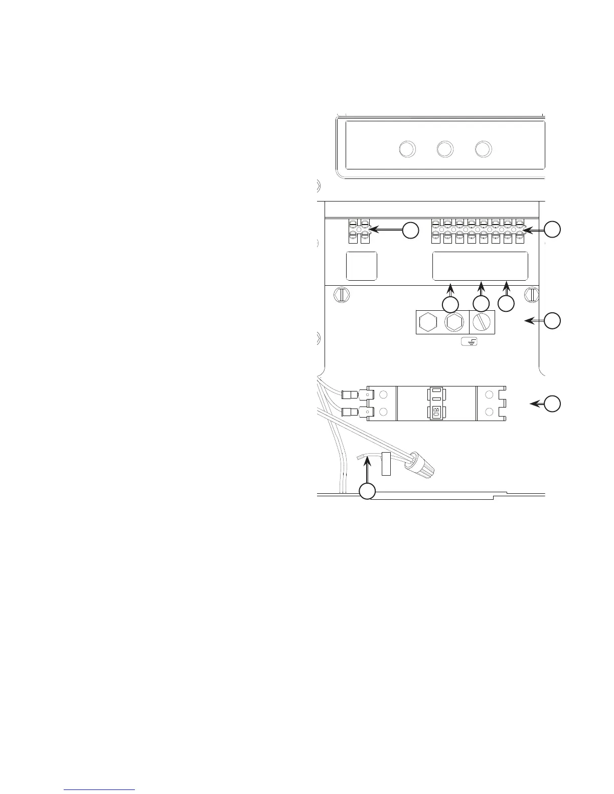
System Connectors
Low Voltage connections to signal fault contacts, transfer switch communication and auxiliary 12VDC power are made via a
field connection terminal block in control board area. Compare this illustration with your generator to familiarize yourself
with the location of these connections.
A - Two Pin Terminal Block — Used to connect utility
240 VAC from fuse block in ATS to the control board.
Connect only one wire per terminal.
B - Fault Contacts — Use NO, COM and NC to hook up a
siren, light, etc. to alert you in case of a fault. Contacts
reverse state (NO goes to NC and vice versa) upon a
fault condition.
C - Transfer Switch Communication (TxRx and TxRx
GND) — Connect to transfer switch control board for
communication interface using 18AWG twisted pair
wire. (Not applicable with all transfer switches.)
D - +LED and GND Connection — Not required for optional
wireless monitor. Available for optional hardwired
remote system status panel accessory, #6154.
E - Eight Pin Terminal Block — Used to connect signal
wires to the control board. Connect only one wire per
terminal.
F - Power Connection (Line 1 and Line 2) — Power
connection to transfer switch.
G - Neutral and/or Ground Connection — Connect to
transfer switch neutral and ground
t'PSQPXFSPVUQVUDPOOFDUJPO
8kw - (Line 1, Line 2, Neutral, and Ground), 300V, 10 AWG copper wire, or 300V, 8 AWG aluminum wire, (ref. NEC Table 310.16, 100 ft
10kw - (Line 1, Line 2, Neutral, and Ground), 300V, 8 AWG copper wire, or 300V, 6AWG aluminum wire, (ref. NEC Table 310.16, 100 ft
t6TF/BUJPOBM&MFDUSJD$PEFGPSDPSSFDUJPOGBDUPSTBOEXJSFTJ[FDBMDVMBUJPOT
t'PSVUJMJUZDJSDVJUDPOOFDUJPO6UJMJUZ"BOE6UJMJUZ#VTF"8(NJOJNVNWPMUXJSF
t'PSUSBOTGFSTXJUDIDPNNVOJDBUJPOVTF"8(UXJTUFEQBJSDPOEVDUPSTOPHSFBUFSUIBOGUJOMFOHUIWPMUXJSF
t8IFODPOOFDUJOHUPUIFUFSNJOBMCMPDLGBTUFOPOMZPOFXJSFUPFBDIDPOOFDUPSTDSFX
t5PSRVFUFSNJOBMCMPDLTDSFXTUPJOMC/FXUPONFUFS
t5PSRVFDJSDVJUCSFBLFSDPOOFDUJPOTUPJOMC/FXUPONFUFS
E
A
F
G
UTILITY
1
UTILITY 2
N.O.
COM
N.C.
TxRx
TxRxGND
+LED
GND
N/C
LINE 1
LINE 2
GND
GROUND
NEUTRAL
[
[
[
[
B
C
D
G
 Loading...