23
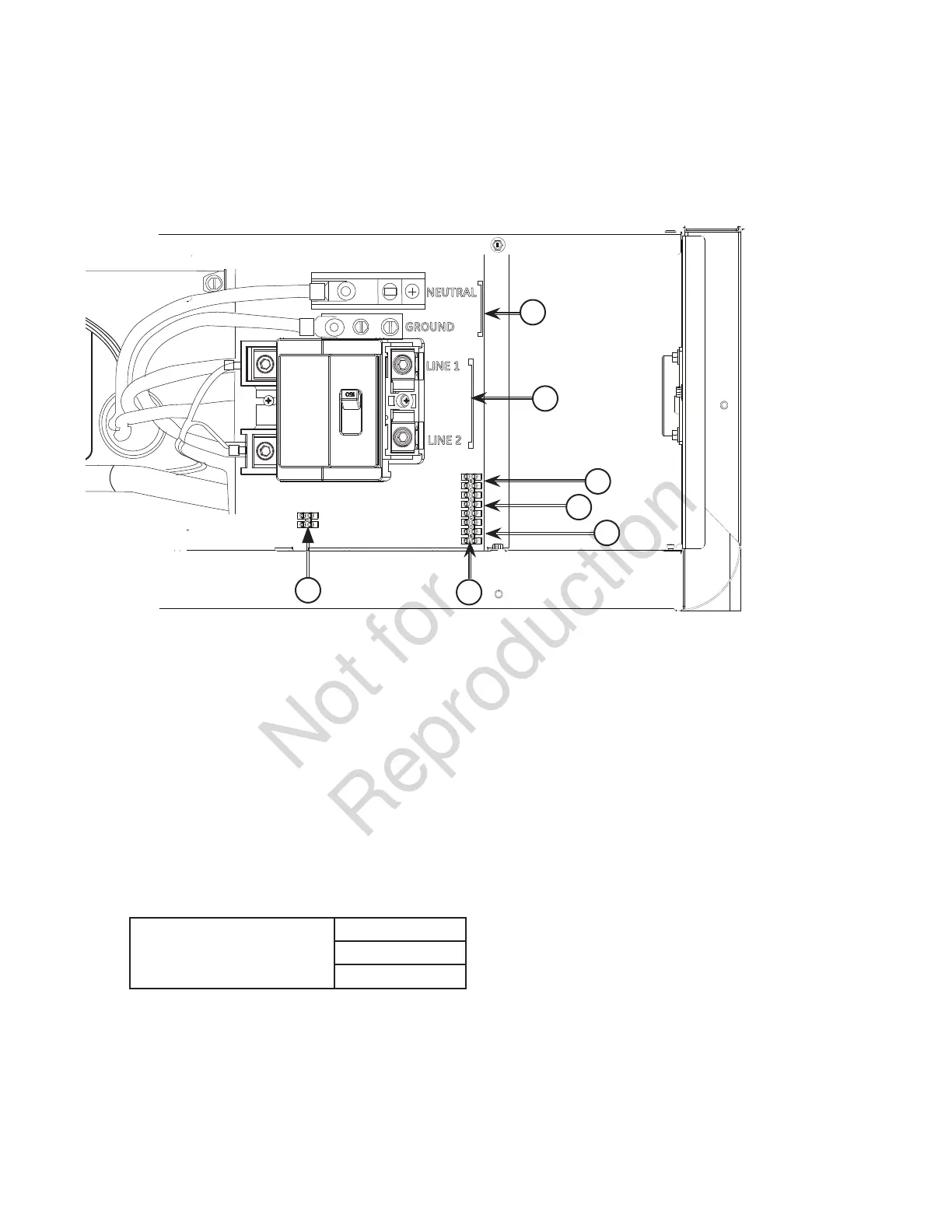
A - Two Pin Terminal Block — Used to connect utility
240 VAC from fuse block in ATS to the control board.
Connect only one wire per terminal.
B - Fault Contacts — Use NO, COM and NC to hook up a
siren, light, etc. to alert you in case of a fault. Contacts
reverse state (NO goes to NC and vice versa) upon a
fault condition.
C - Transfer Switch Communication (TxRx and TxRx
GND) — Connect to transfer switch control board for
communication interface using 18 AWG twisted pair
wire.
D - +LED and GND Connection — Not required for optional
wireless monitor #6229. Available for optional
hardwired remote system status panel accessory,
#6154.
E - Eight Pin Terminal Block — Used to connect signal
wires to the control board. Connect only one wire per
terminal.
F - Power Connection (Line 1 and Line 2) — Power
connection to transfer switch.
G - Neutral and Ground Connection — Connect to transfer
switch neutral and ground
System Connectors
Compare this illustration with your generator to familiarize yourself with the location of these connections.
LINE 1
LINE 2
GROUND
NEUTRAL
]
]
E
F
G
B
C
D
A
• For power output connection (Line 1, Line 2, Neutral, and Ground), refer to the following table:
Power output connections
minimum 300V, 75°C
25 kW
1/0 Copper
3/0 Aluminum
• Reference NEC 2011 table 310.15 (B) (16)
• Use National Electric Code for correction factors and wire size calculations.
• For utility circuit connection (Utility A and Utility B) use #14 AWG minimum 300 volt wire.
• For transfer switch communication use #18 AWG twisted pair conductors, no greater than 200 ft in length, 300 volt wire.
• When connecting to the terminal block, fasten only one wire to each connector screw.
• Torque terminal block screws to 4.4 in-lb (0.49 Newton meter).
• Torque circuit breaker connections to 45 in-lb (5 Newton meter).
 Loading...