25
Grounding the Generator
The home generator must be installed as part of a system
that includes a listed transfer switch, with neutral to ground
bonding at the transfer switch in accordance with installation
instructions. Unless mandated by local code, additional
grounding to earth at the generator is not required. Any
grounding at generator must use metal piercing lock
washers (or equal), UL listed terminals installed per terminal
supplier’s instructions, and comply with national electrical
codes and local requirements.
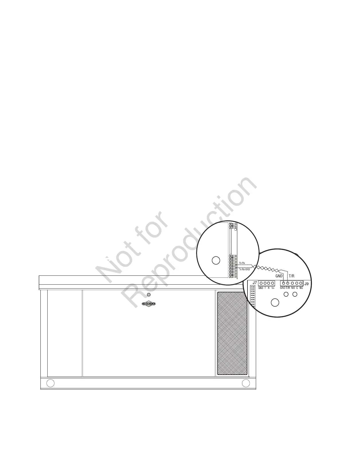
Utility Circuit Connection
“240V Utility” leads must be routed in conduit. The “240V
Utility” leads deliver power to the generator’s circuit board.
This power also charges the battery. When power on the
leads is lost, the generator will start.
Using installer-supplied minimum 300 V, 14 AWG copper
wire*, connect each control circuit terminal (A) in the
generator (Utility A and Utility B) to the fuse block (B) in the
automatic transfer switch.
*Use National Electric Code for correction factors and wire
size calculations.
B
A
 Loading...