3 - 55
Main parts
Application of Assembly
Application
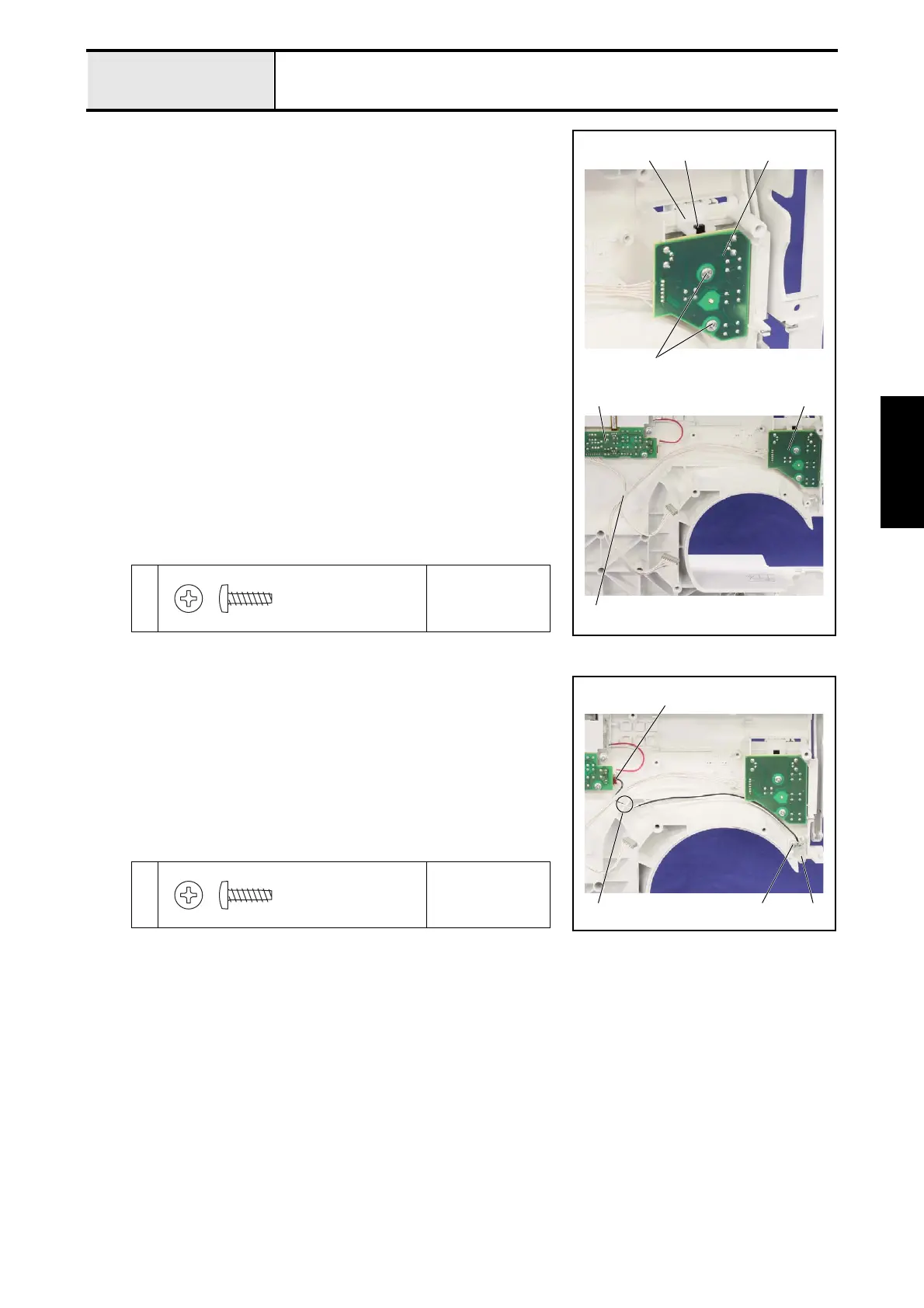
2-11Attachment of SSVR PCB assy
1. Set the SSVR PCB assy. 1 to the front cover assy. with the 2 screws 1.
*Key point
• Check that the speed volume 2 engaged with the groove of
the SV joint plate 3.
• Check that the contact each button to each switch of the
SSVR PCB assy. 1.
2. Bind the lead wires of the SSVR PCB assy. 1 and the operation PCB assy.
4 with the band 5.
*Key point
• Refer to "Special Instructions of Wiring".
1
Torque
0.59 – 0.78 N·m
1
1
23
4
5
1
Taptite, Bind B
M3X10
2-12Attachment of LED lamp assy
1. Set the LED lamp assy. 1 to the front cover assy. with the screw 1.
2. Connect the connector 2 of the LED lamp assy. 1 to the operation PCB
sub assy..
3. Hang the lead wire of the LED lamp assy. 1 on the slit 3 of the front
cover assy..
1
Torque
0.39 – 0.78 N·m
2
113
Taptite, Bind B
M3X10
 Loading...