10
BOAT RIGGING
REMOTE CONTROLS
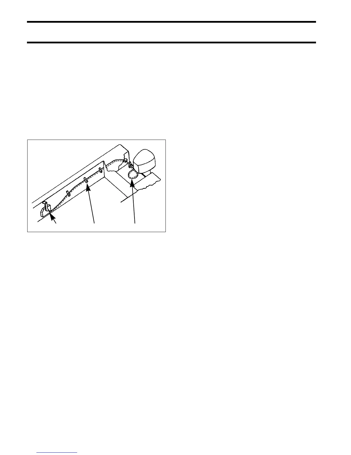
Control Cable Routing
Control cables and harnesses should be routed
along a protected path to the rear of the boat and
secured to prevent movement or damage.
Harness connections should be mounted in a dry
location, away from bilge and motor well areas.
Control cables should be long enough to allow a
12 in. (30 cm) cable loop at the front of the out-
board when the cables are routed from the side of
the splash well.
Evinrude ICON Networks
All control information is transferred between the
outboard and an Evinrude ICON system through a
single network cable. For complete installation
instructions, refer to the Evinrude ICON Remote
Control System Installation Guide, P/N 764952.
When installing an ICON network, remember:
• Control network must include two cable hubs
• DO NOT use the key switch to power accesso-
ries (switched B+)—use an ICON Accessory
Power Relay Kit
• The ICON Gateway provides a connection for
an I-Command Information Display network.
Refer to Evinrude ICON / I-Command Harness
Connections on p. 14 for a typical network instal-
lation diagram.
1. Surface side-mount remote control
2. Cable support
3. 12 in. (30 cm) cable loop at front of outboard
DR4277
 Loading...