12
BOAT RIGGING
INFORMATION DISPLAY SYSTEMS
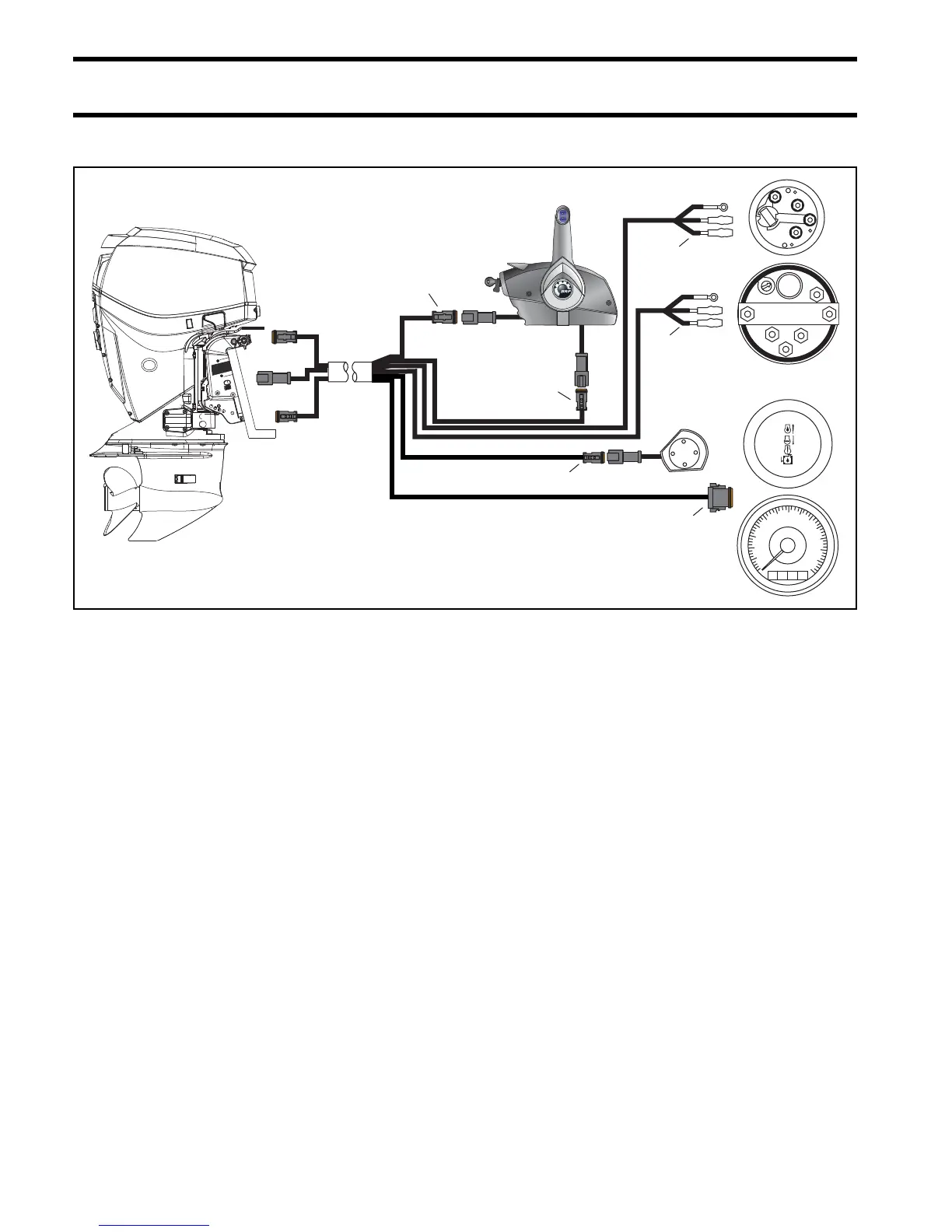
SystemCheck (MWS) Harness Connections
NO OIL
WATER TEMP
CHECK ENGINE
LOW OI L
2
5
6
4
3
PUL
REV
PUL
GND
+12V
0
2
1
3
4
5
6
7
1
2
3
4
5
6
G
I
S
G
I
S
Typical MWS wiring with a side-mount mechanical remote control 007989
1. 6-Pin Connector – Connect to a pre-wired remote control or to a dash-mounted key switch.
2. 3-Pin Connector – Connect to remote control trim switch or to a dash-mounted trim switch.
3. Black, purple, white/tan wires – Connect to the trim gauge.
4. Black, purple, gray wires – Connect to a conventional tachometer when a SystemCheck tachom-
eter is not used.
5. 2-Pin Connector – Must connect to the warning horn in all installations.
6. 8-Pin Connector – Connect to a SystemCheck gauge or tachometer.
 Loading...