17
BOAT RIGGING
BATTERY INSTALLATION
1
Battery Switch Operation
• Select the primary battery for normal operation.
• Secondary batteries should only be selected for
emergency starting.
• ALL or BOTH switch position is for emergency
starting only.
Provide operator with the documentation sup-
plied by the battery switch manufacturer. Make
sure that the operator is informed of proper
battery switch operation.
The negative (–) terminals of a mul-
tiple 12-volt battery installation must be con-
nected together.
Auxiliary Battery Charging
EVINRUDE E-TEC V4 – V6 MODELS
Evinrude E-TEC V4–V6 outboards are equipped
with isolated battery charging capability. The iso-
lated charge connection must only be used to
charge a single 12-volt battery or two 12-volt bat-
teries wired in parallel.
Never connect an external battery
isolator to the stator of an Evinrude E-TEC.
Accessory Charge Lead Kit, P/N 5006253, is
routed from a connector on the outboard’s electri-
cal harness to the accessory battery.
The accessory charging kit must
never be connected to any battery of a 24-volt
electrical system.
EVINRUDE E-TEC 40 – 90HP MODELS
Evinrude E-TEC 40 – 90 HP outboards do not
have a built in isolator feature. Proper methods
must be used to connect a second battery.
Battery charging output on 40 – 90 HP models is
25 Amps. Be sure to follow published standards
for wire gauge selection. Refer to Battery Cable
Requirements on p. 16.
If a battery isolator is desired, a battery switch,
such as P/N 506161, and a voltage sensitive
relay, such as BEP model 710-125A, can be used
to create a battery isolator/combiner.
The voltage sensitive relay (VSR) regulates
charging of a second battery based on predeter-
mined voltage levels of the primary battery.
Never connect an external battery
isolator to the stator of an Evinrude E-TEC.
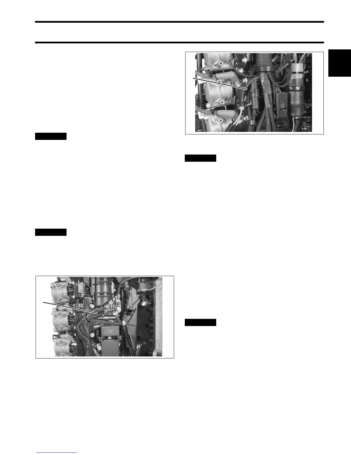
90° V6 Models
1. Accessory battery charge connector
004125
60° V4–V6 Models
1. Accessory battery charge connector
004944
 Loading...