32
OUTBOARD INSTALLATION
HULL PREPARATION
Transom Brackets and Jack
Plates
When mounting an outboard on a jack plate:
• Refer to the manufacturer's recommendations
for maximum weight and horsepower.
• The jack plate must provide a rigid, one-piece
mounting assembly—either a solid surface, or
surfaces adequately connected to prevent flex-
ing or twisting.
• DO NOT use a jack plate constructed in two
separate pieces—lack of support can twist the
stern brackets, wear tilt tube bushings and
thrust rollers, and bend or break components.
IMPORTANT: Damage caused by use of a two-
piece jack plate or unstable mounting surface will
not be covered by warranty.
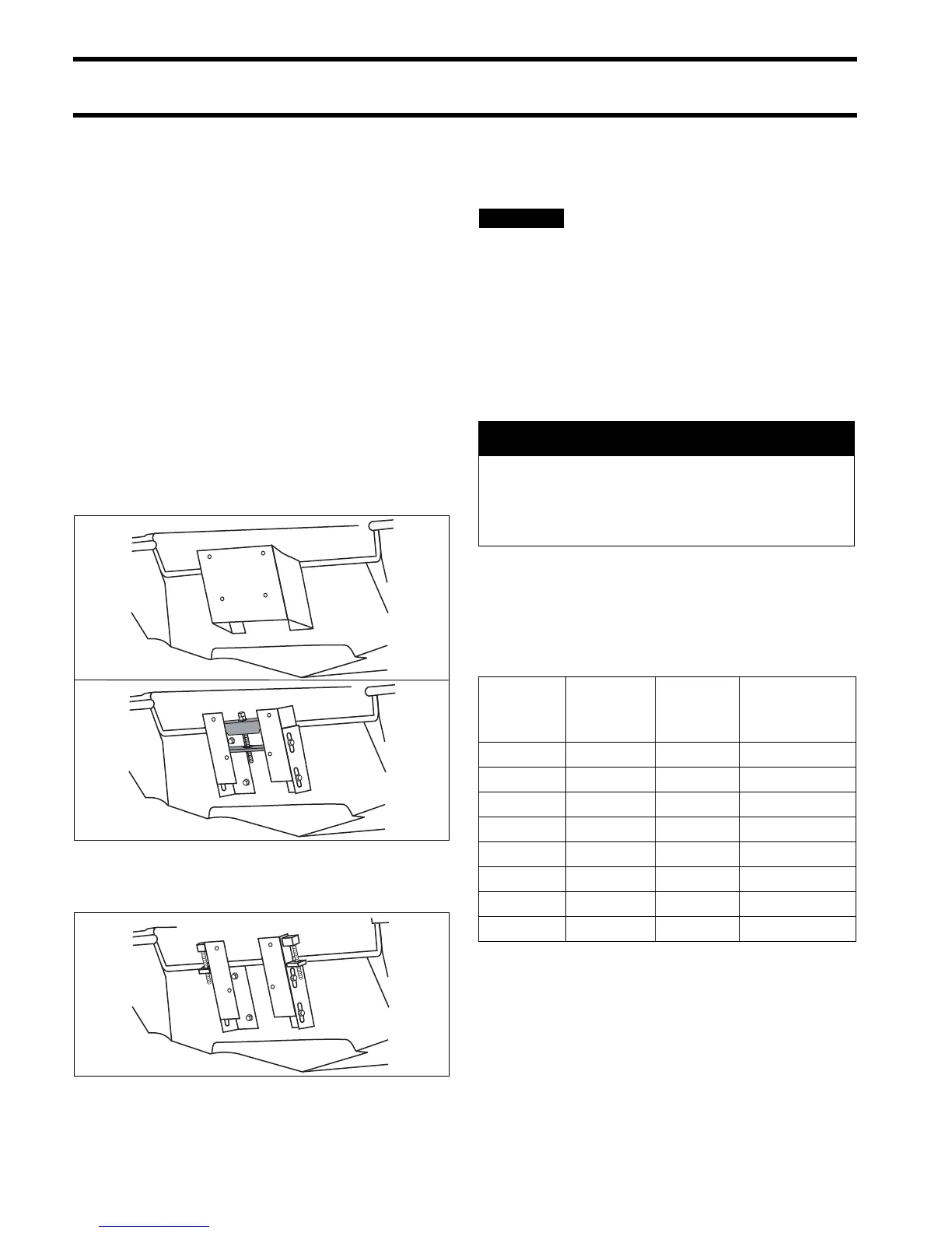
Recommended Designs
Not Recommended
Whenever possible, use mounting hardware sup-
plied with the outboard to install jack plate on tran-
som. Tighten to a torque of 40 ft. lbs. (54 N·m).
To prevent damage to outboard,
check installation frequently for:
• Loose mounting bolts and nuts
• Loose tilt tube or steering cable nuts
• Elongated mounting holes
• Bent or deformed washers
Replace any hardware that fails to maintain
torque specifications.
Mounting Hardware
Outboard mounting hardware must meet mini-
mum specifications for material and strength:
• Material: Stainless steel; Group 1,2,3 per
ASTM F593 OR Grade A2 per ISO 3506-1.
• Strength: Minimum proof load.
Outboard mounting bolts, backing plates, wash-
ers, and nuts are used to attach the outboard to
the shipping pallet. If alternate bolt lengths or
replacement parts are required, use only
Evinrude/Johnson Genuine Parts.
IMPORTANT: Standard screws offered by local
merchants may not provide the high strength
required for outboard installations.
007992 007991
DR5703
A WARNING
Use all mounting hardware supplied with
the outboard to help ensure a secure
installation. Substituting inferior hardware
can result in loss of control.
Part
Number
Length
(inches)
Thread
Size
Proof Load
Minimum
(lbs.)
327053 3 1/2-13 18,520
318573 3.5 1/2-13 12,771
336676 4.75 1/2-13 12,771
331578 5 1/2-13 18,520
354101 6 1/2-13 18,520
354102 7 1/2-13 18,520
354103 8 1/2-13 18,520
354104 9 1/2-13 18,520
 Loading...