11
A.
General Guidelines.
1. Vent system installation must be in accordance with
National Fuel Gas Code, NFPA 54/ANSI Z221.3,
Part 7, Venting of Equipment; and/or CAN/CGA
B149 Installation Codes, Section 7, Venting Systems
and Air Supply for Appliances; or applicable
provisions of local building codes. Contact local
building or fi re offi cials about restrictions and
installation inspection in your area.
2. This appliance requires a Special Gas Vent. Use
Vent Connector and Vent Terminal in Vent
Accessory Carton provided with boiler (See Repair
Parts, Key No. 8). The product is designed to use
Burnham supplied AL 29-4C
®
Stainless Steel vent
system components. The following manufacturers
offer similar AL 29-4C
®
components and are
approved for use with this product: Heat-Fab Inc. -
Saf-T-Vent, Flex-L International Inc., - Star-34,
Protech Systems, Inc. - FasNSeal™, and Z-Flex U.
S., Inc. - Z-Vent. The use of these alternate
manufacturer's venting systems will require adapters
to connect to the Burnham supplied vent connector
and vent terminal. These adapters are not supplied
with this unit and should be obtained from the
supplier of the alternate manufacturer's venting
system. See Table 5 for complete list of Burnham
Vent System Components.
3. Vent length restrictions are based on equivalent feet
of vent pipe (total length of straight pipe in feet plus
5 equivalent feet for each 45° or 90° elbow). Do not
exceed the maximum certifi ed vent length of 25
equivalent feet. The minimum certifi ed vent length
is 7 equivalent feet. Do not include vent terminal or
vent connector in equivalent feet calculations.
4. Do not install venting system components on the
exterior of the building except as specifi cally
required by these instructions.
5. This 2PV boiler may only be sidewall vented; it may
not be vertically vented, as through a roof.
B. Removal of Existing Boiler. For installations not
involving the replacement of an existing boiler, proceed
to Step C.
When an existing boiler is removed from a common
venting system, the common venting system is likely to
be too large for proper venting of the remaining
appliances. At the time of removal of an existing boiler,
the following steps shall be followed with each
appliance remaining connected to the common venting
system placed in operation, while the other appliances
remaining connected to the common venting system are
not in operation:
1. Seal any unused openings in the common venting
system.
2. Visually inspect the venting system for proper size
and horizontal pitch and determine there is no
blockage or restriction, leakage, corrosion, and other
defi ciencies which could cause an unsafe condition.
3. Insofar as is practical, close all building doors and
windows and all doors between the space in which
the appliances remaining connected to the common
venting system are located and other spaces of the
building. Turn on clothes dryers and any appliance
not connected to the common venting system. Turn
on any exhaust fans, such as range-hoods and
bathroom exhausts, so they will operate at maxi mum
speed. Do not operate a summer exhaust fan. Close
fi replace dampers.
4. Place in operation the appliance being inspected.
Follow the Lighting (or Operating) Instructions.
Adjust thermo stat so appliance will operate
continuously.
5. Test for spillage at the drafthood relief opening after
5 minutes of main burner operation. Use the fl ame
of a match or candle, or smoke from a cigarette,
cigar or pipe.
6. After it has been determined that each appliance
remain ing connected to the common venting system
properly vents when tested as outlined above, return
doors, win dows, exhaust fans, fi replace dampers and
any other gas burning appliance to their previous
conditions of use.
7. Any improper operation of the common venting
system should be corrected so the installation
conforms with the National Fuel Gas Code, NFPA
54/ANSI Z223.1. When resizing any portion of the
common venting system, the common venting
system should be resized to approach the minimum
size as determined using the appropriate tables in
Part II in the National Fuel Gas Code, NFPA 54/
ANSI Z223.1.
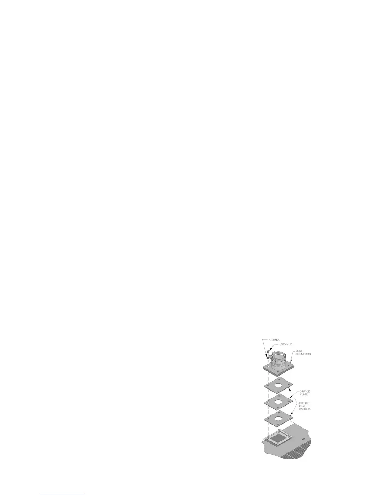
C. Install Vent Connector.
1. Remove vent connector from vent accessory carton.
2. Remove gaskets, orifi ce plate and hardware from
blower outlet fl ange.
3. Assemble orifi ce plate gaskets, orifi ce plate, and
vent connector. See Figure 7.
4. Secure vent connector with washers and locknuts.
Figure 7: Vent Connector Installation
 Loading...