16
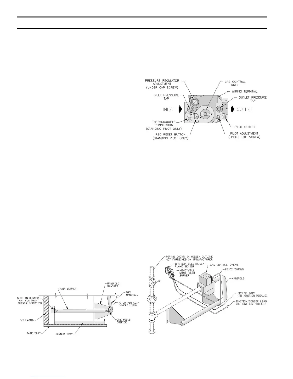
Figure 12: Gas Valve Pressure Tap
3. For natural gas fi red boiler, temporarily turn off all
other gas-fi red appliances.
E. Follow Operating Instructions to place boiler in
operation. See Figure 17.
F. Sequence of Operation. See Figure 14. If boiler fails
to operate properly, see Troubleshooting Tree on pages
20-22.
G. Check gas piping and connections between Gas Valve
and Manifold, Orifi ces and Pilot Tubing. Use soap
solution or other approved method. See Figure 13.
Figure 13: Schematic Pilot and Gas PipingFigure 11: Main Burner Installation
VII. System Start-up
A. Safe operation and other performance criteria were
met with gas manifold and control assembly provided
on boiler when boiler underwent tests specifi ed in
American National Standard for Gas-Fired Low-
Pressure Steam and Hot Water Boilers, ANSI Z21.13.
B. Fill heating system with water and vent air from
system. Use the following procedure on a Series Loop
System equipped with zone valves. See Figure 3.
1. Close isolation valve in boiler supply piping.
2. Isolate all circuits by closing zone valves or
balancing valves.
3. Attach hose to hose bib located just below isolation
valve in boiler supply piping. Terminate hose in fi ve
gallon bucket at a suitable fl oor drain or outdoor
area).
4. Starting with one circuit, open zone valve.
5. Open hose bib.
6. Open fi ll valve. Makeup water line should be
located directly above isolation valve in boiler
supply piping.
7. Allow water to overfl ow from bucket until discharge
from hose is bubble free for 30 seconds.
8. Open zone valve to second zone to be purged, then
close fi rst. Repeat this step until all zones have been
purged, but always have one zone open. At
completion, open all zone valves.
9. Close hose bib, continue fi lling system until pressure
gauge reads 12 psi. Close fi ll valve.
Note: If makeup water line is equipped with
pressure reducing valve, system will automatically
fi ll to 12 psi. Leave globe valve open.
10. Open isolation valve in boiler supply piping.
11. Remove hose from hose bib.
C. Check main burners. See Figure 11. Rear of burner
must be in vertical slot in rear of burner tray. Front of
burner must be seated on orifi ce.
D. Prepare to check operation.
1. Obtain gas heating value (in Btu per cubic foot)
from gas supplier.
2. Connect manometer to pressure tap on gas valve.
See Figure 12.
 Loading...