p. 6 - Manual FA01313-EN - 02/2019 - © CAME S.p.A. - The contents of this manual may change, at any time, and without notice. - Original instructions
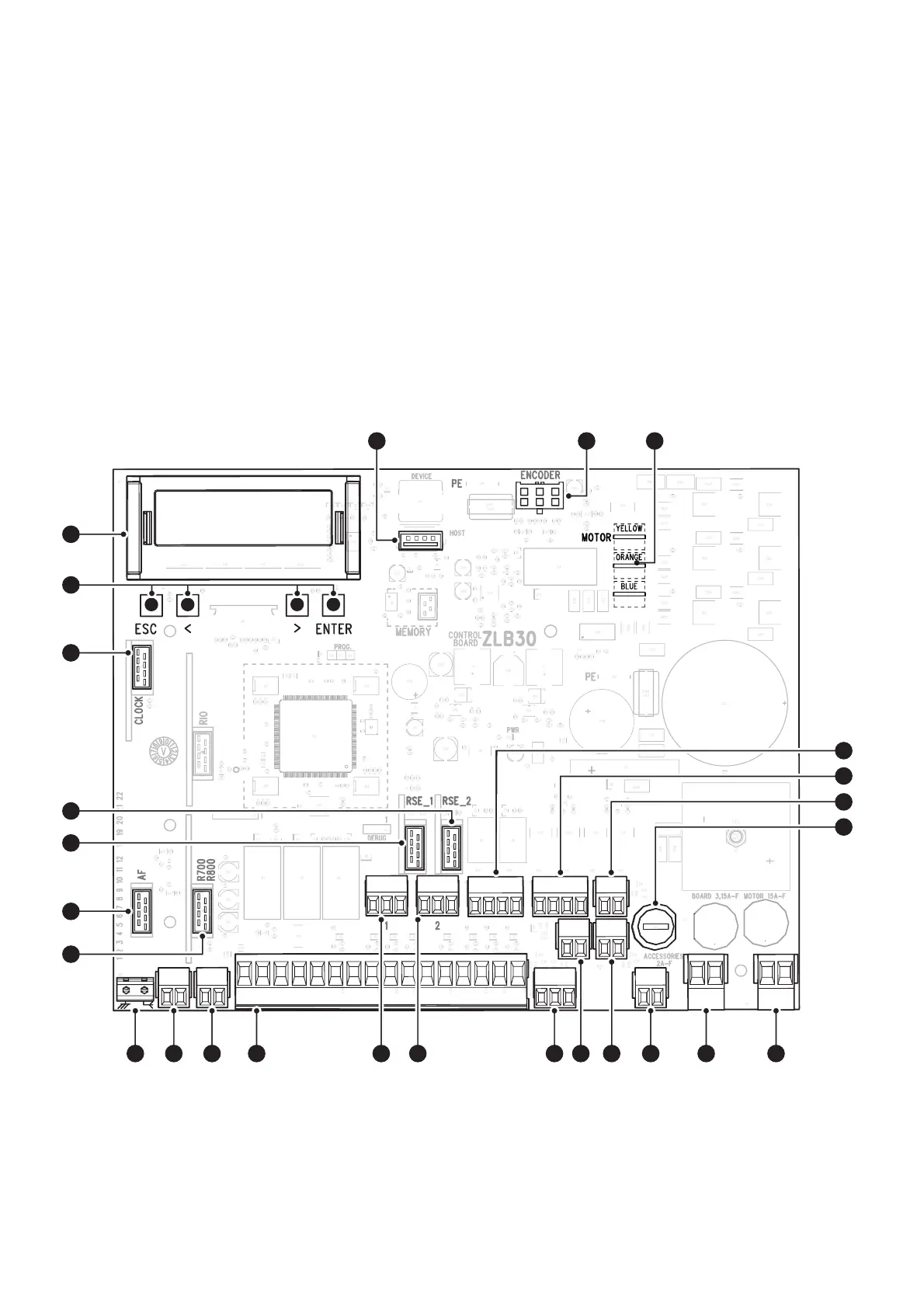
Control board
1 - Buttons for programming
2 - Display
3 - USB stick connector
4 - Encoder connector
5 - Motor connector
A p.n. ferrite is applied to the cable ECQK922091
6 - Terminal board for barrier status
7 - Terminal block for connecting the warning LED strip
8 - Terminal board not used
9 - Accessories fuse
10 - Terminal block for motor power supply
11 - Terminal board for power supply to the control board
12 - Terminal block for connecting the open cover safety microswitch (NC
contact)
13 - Terminal board for NC contact for boom drop away
14 - Terminal board for connecting the unlocked gearmotor safety microswitch
(NC contact)
15 - Terminal boards for connecting travel end microswitches (NC contact) *
16 - Terminal board associated with the RSE_2 connector for CRP connection,
IO 485 card or Modbus RTU interface
17 - Terminal board associated with the RSE_1 connector for combined
connection, alternate or CRP
18 - Terminal board for connecting control and safety devices
19 - Terminal board for connecting the keypad selector
20 - Terminal board for connecting the transponder selector
21 - Terminal board for connecting the antenna
22 - Connector for the R700 or R800 decoding card
23 - Connector for plug-in radio frequency card (AF)
24 - RSE_1 connector for RSE card
25 - RSE_2 connector for RSE card
26 - Connector for the clock card (806SA-0120)
* Used only for GPX40MGP
A B GND A B GND R G B
2
24
10
S1 GND
AB
11 E1 E6 TS 1 2 3 3P 4 5 7 2 CX CY CZ
0300
FA
FC
TAMPER
FCA CM1 FCC CM2
EB
MOTOR
BLOCK
ARM
EB+
2
26
24
23
21 20 19 18 15 14 131617 12 11 10
3 544
22
25
6
7
8
9
1

 Loading...