9
ENGLISH
The data and information provided in this manual are to be considered susceptible to change at any time without warning, by CAME cancelli automatici s.p.a.
EN
Antenna connection - cable RG58
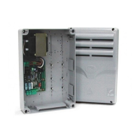
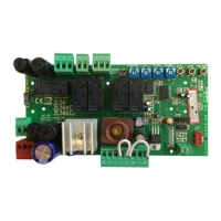
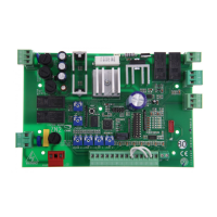
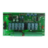
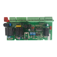
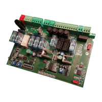
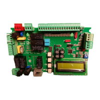
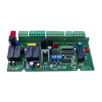
Electrical connections
Contact (N.C.) for re-opening during closure
(should be short circuited if not used)
10-11
2-7
2-C3
1-2
10-5
2-C1
L1-L2
Power supply for control unit 230V (a.c.) Stop button (N.C.)
Connector (N.O.) radio and/or pushbutton
Power supply to accessories (max. 40W):
- 24V (a.c.) with power supply at 230V (a.c.)
- 24V (d.c.) with power supply at 24V (d.c.)
Partial stop contact (N.C.)
24V-3W max. gate-open signal lamp
Control panel/gear motor connections ( ADT card )
10-E
11-S
24V-25W max. output in motion (e.g. flashing light)
2-3
Open button (N.O.)
A1-A2
Contact outlet (N.O.): it is closed for 3” upon opening command.
Contact capacity: 5A (250V AC)
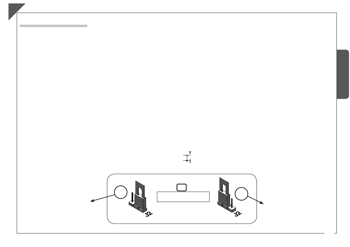
Jumper J2
M-N-R
B
A
- JUMPER IN POSITION A (default)
24V - 25W max cycle indicador
light
-
JUMPER IN POSITION B
Contact output (N.O.) 2
nd
radio
channel
Contact capacity: 1A to 24V d.c.
10-E3
B1-B2
Connection for electrically-actuated lock: 12V-15W max.
T-T
Transformer Heat Overload trip contact
a
9
ENGLISH
The data and information provided in this manual are to be considered susceptible to change at any time without warning, by CAME cancelli automatici s.p.a.
EN
Antenna connection - cable RG58
Electrical connections
Contact (N.C.) for re-opening during closure
(should be short circuited if not used)
10-11
2-7
2-C3
1-2
10-5
2-C1
L1-L2
Power supply for control unit 230V (a.c.) Stop button (N.C.)
Connector (N.O.) radio and/or pushbutton
Power supply to accessories (max. 40W):
- 24V (a.c.) with power supply at 230V (a.c.)
- 24V (d.c.) with power supply at 24V (d.c.)
Partial stop contact (N.C.)
24V-3W max. gate-open signal lamp
Control panel/gear motor connections ( ADT card )
10-E
11-S
24V-25W max. output in motion (e.g. flashing light)
2-3
Open button (N.O.)
A1-A2
Contact outlet (N.O.): it is closed for 3” upon opening command.
Contact capacity: 5A (250V AC)
Jumper J2
M-N-R
B
A
- JUMPER IN POSITION A (default)
24V - 25W max cycle indicador
light
-
JUMPER IN POSITION B
Contact output (N.O.) 2
nd
radio
channel
Contact capacity: 1A to 24V d.c.
10-E3
B1-B2
Connection for electrically-actuated lock: 12V-15W max.
T-T
Transformer Heat Overload trip contact
a
 Loading...