16
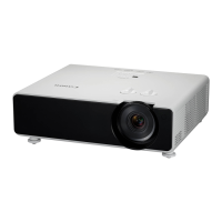
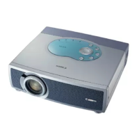
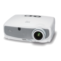
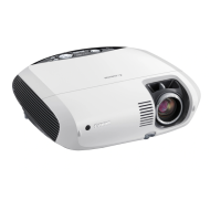
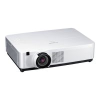
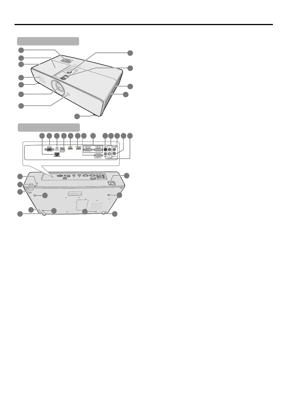
Projector exterior view
1. External control panel
(See "Projector" on page 17 for details.)
2. Lamp cover
3. Vent (heated air exhaust)
4. Speaker
5. Adjuster foot
6. Projection lens
7. Front IR remote sensor
8. Lens shift wheel
9. Focus ring and Zoom ring
10. Vent (air intake)
11. Filter cover
12. LAN port/HDBaseT input terminal
13. CONTROL port
14. SERVICE port**
15. USB power out
16. HDMI input terminal
17. HDMI/MHL input terminal
18. Monitor output terminal
19. PC input terminal x 2
20. S-Video input terminal
21. Audio input terminal (RCA)
22. Audio input terminal (stereo mini jack)
23. Audio output terminal (stereo mini jack)
24. Video input terminal
25. Kensington lock
26. Security bar
27. AC power cord inlet
28. Ceiling mount holes
29. Release button of the filter cover
** By connecting the projector and computer via USB,
you can operate the computer from the remote controller
(Page UP/Page DOWN).
27
5 5
28
28
28
28
26
29
29
25
14
12 13
15 16 17 18
1
9
22 23 242120
 Loading...