E10
5. Details of Operation and Functions
5-1. Pan-Tilt Head
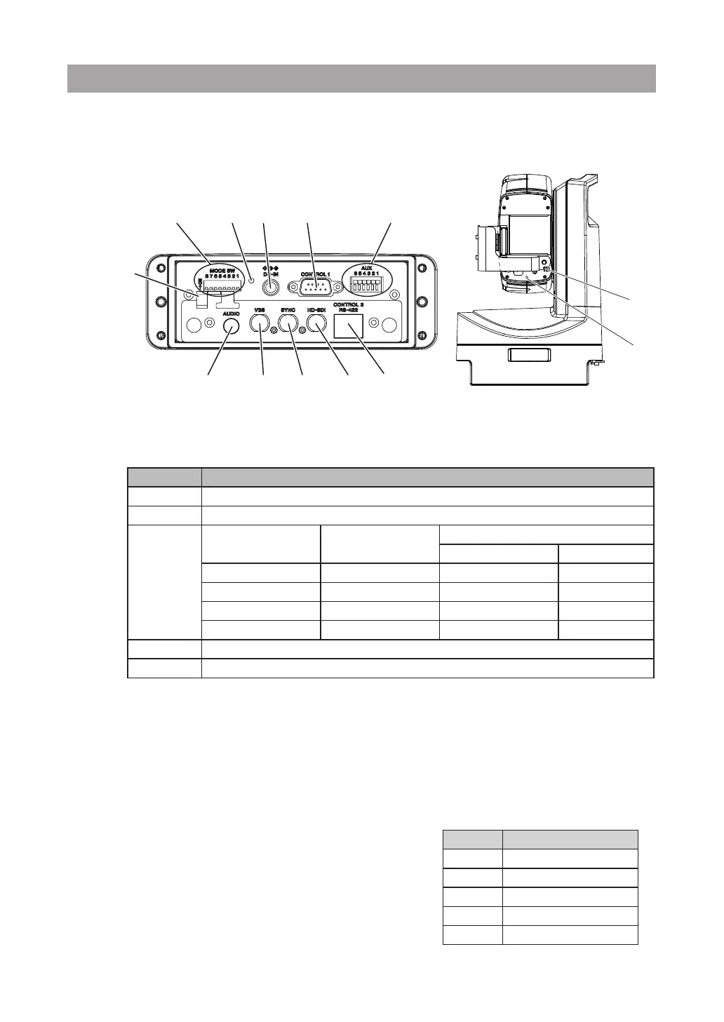
5-1-1. Control Connectors
[Receptacle unit in the rear of the pan-tilt head]
①
MODE SW
Specify the transmission mode, installation type, and image format. After any changes, restart
the unit.
Switch Setting Details
1 Transmission mode (OFF: RS-232C, ON: RS-422)
2 Installation type (OFF: upright installation, ON: suspended from a ceiling)
3
,
4
3
(
59.94/50
)
4
(
1080i/720p
)
Image Format
HD-SDI VBS
OFF OFF 1080/59.94i NTSC
ON OFF 1080/50i PAL
OFF ON 720/59.94p NTSC
ON ON 720/50p PAL
5 to
7 Not used. Leave the switch set to OFF.
8 OFF: Normal mode, ON: high-speed mode
②
PWR LED
Lit in green when on.
③
DC-IN
Inlet for supplying DC power. Using the included power cord, connect the unit to a DC power
source suitable for the location of installation. (12 V, 30 W or more capacity recommended.)
④
RS-232C (see pin assignment at right)
A
n input for remote control. Connect one end of
an RS-232C cable here and the other end to the
operation unit.
Ensure that the cable connector can t through an
opening 36.5 mm in diameter.
DC cable
fastener
①
⑤
② ③
④
⑥
⑦
⑧
⑨
⑩
⑫
⑪
④
RS-232C
(
D-sub9P
:
DTE
)
Pin No. Signal
2 RD (IN)
3 SD (OUT)
4 ER (xed at +12V)
5 GND
7 RS (xed at +12V)
To connect a computer, use a cross-cable.
 Loading...