11
BATTERY CHARGING, Cont.
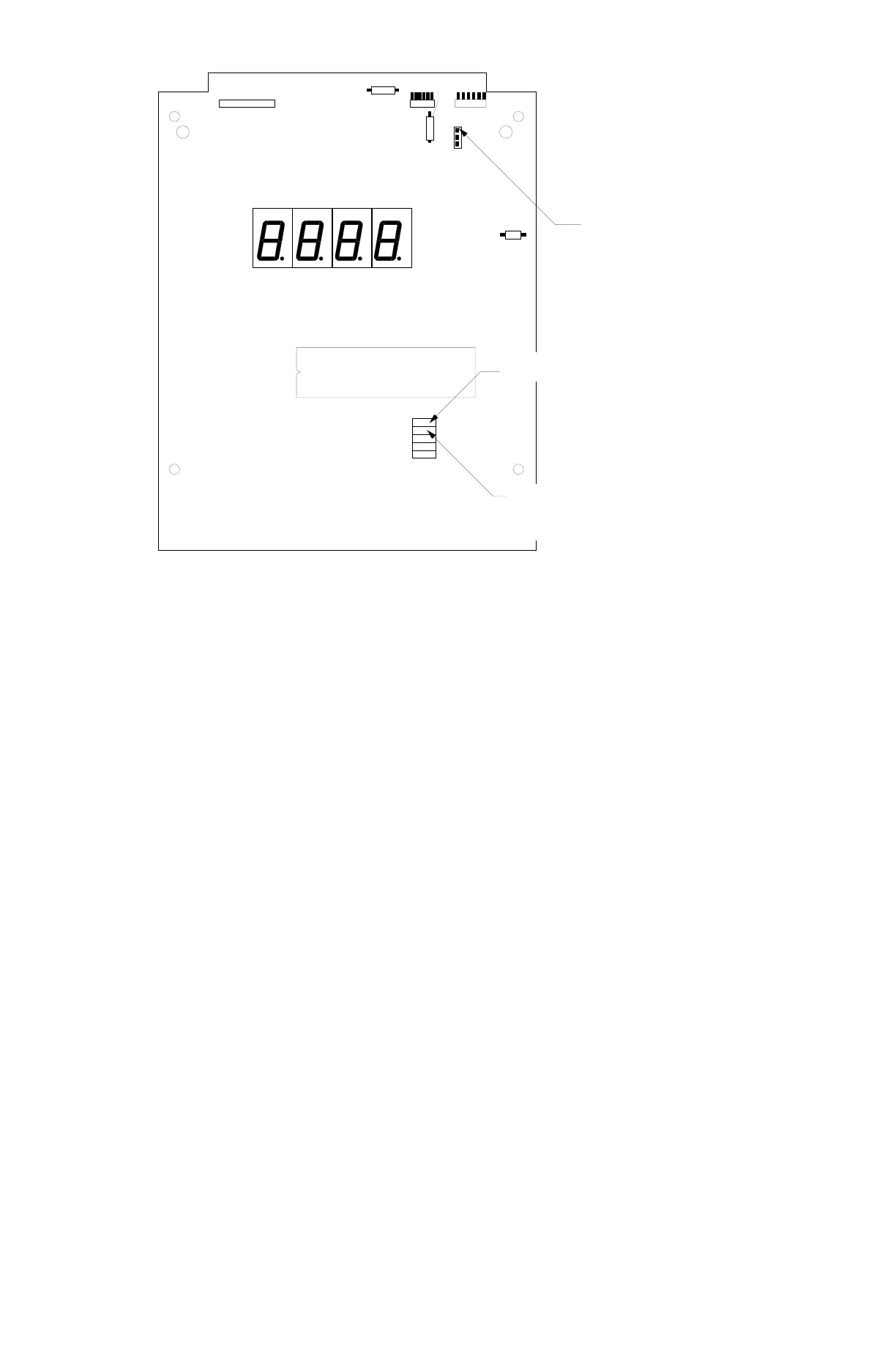
Figure No. 9
P3
P2
P1
D1
OFF ON
D3
J1
J7
J6
U18
J8
J9
J10
J11
Numeric Keypad
Enabled
International Application
(causes the power up
sequence to include
memory and display test)
Install Jumper for
Ni-Cad batteries.
Remove Jumper for
Alkaline Batteries
PRINTED CIRCUIT BOARD JUMPER TABLE
FACTORY SETUP
CN20E CN20L PCB Side Shorted Function
LED LCD Location Function
J1 Open Open Component (Battery Charger Enable)
J6 Open Open Component (Auto-on)
J7 *Open *Open Component (Numeric Keypad Enable)
J8 Open Open Component (International Application)
J10 Shorted Open Component (LED Select)
J11 Open Open Component (Test Mode Select)
Refer to Figure No. 9
*Shorted if equipped with numeric keypad.
ERROR AND STATUS DISPLAYS
The CN20 is equipped with a diagnostic software program that tests various portions of the
instrument’s circuitry and verifies proper operation. Should a problem be detected, an error or status
message will be displayed alerting the operator to that condition. The following lists these errors and
status displays and their meaning:
Display Meaning
UnSt Motion is present when the CN20 is attempting
to perform one of the following operations:
Power Up
Zero Weight Display
UnLd The weight on the scale platform exceeds the
zero range on Power On.
LoAd The scale deadload is less than the zero range
on Power On.

 Loading...