3
INSTALLATION, Cont.
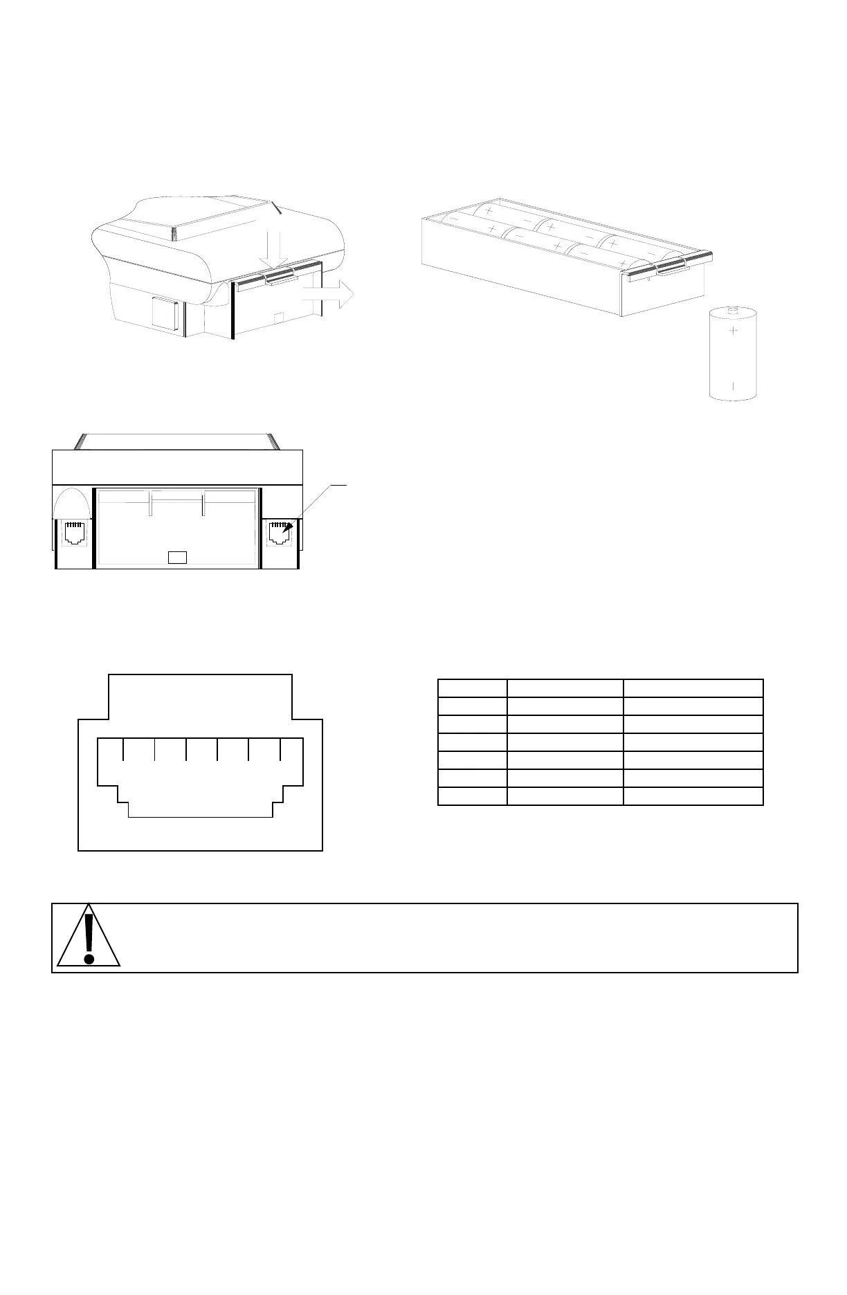
Alkaline batteries will last several months in an instrument with a LCD display. They will last only a
couple of days in an instrument with a LED display. Therefore, it is recommended that rechargeable
Ni-Cad batteries be used in instruments with LED displays.
The battery charging circuitry is disabled. Should you wish to enable or disable your battery charger,
please contact your scale serviceman.
Press
Pull
Remove Battery Drawer Install Batteries as Shown
Figure No. 3
LOAD CELL CONNECTIONS
The load cell connection to the CN20 is made
via a 6-PIN modular type connector located on
the rear panel of the enclosure. Refer to Figure
no. 4 for the location of this connector. Your
scale should be equipped with a cable
terminated in a modular type connector. This
connector should be inserted into the mating
connector on the rear of the CN20 until it locks
into place.
If you are connecting the CN20 to a scale without a modular connector, it will be necessary to modify
the scale cable by installing a 6-conductor modular connector. Refer to the detail figure and table
below for identification of the wires from this connector.
PIN # SIGNAL WIRE COLOR
1 N.C.
BLUE*
2 N.C.
YELLOW*
3 +EXC GREEN
4 +SIG RED
5 -EXC BLACK
6 -SIG WHITE
SETUP AND CALIBRATION
If you received your CN20 already installed on a scale, calibration is not required. Your
scale was calibrated at the factory.
Before beginning the setup and calibration of your CN20, first make certain that it has been installed
in accordance with the instructions given in this manual. Remove the two (2) front screws from the
bottom of the enclosure and loosen the rear two (2). Make certain the CN20 has been turned off then
lift upward on the rear of the top enclosure to expose the calibration switch. Refer to Figure no. 5 for
the identification and location of this switch.
Press the calibration switch and hold it while pressing the ON key on the instrument’s keyboard.
Release the calibration switch. If the display shows int= the CN20 is ready for setup and
calibration. If, however, the display is blank the following should be checked:
1. If using the optional AC plug-in power supply, verify that the mating connector is fully seated in
the power jack on the bottom of the instrument housing and that the power supply is plugged
into a working outlet.
Scale
Input
(See Detail)
1 2 3 4 5 6
Figure No. 4
Load Cell Connector Wiring
N.C. = no connection
*Blue and Yellow wire not used

 Loading...