8
ENG
“EVD ice” +0300038EN - rel. 1.1 - 23.04.2018
2. INSTALLATION
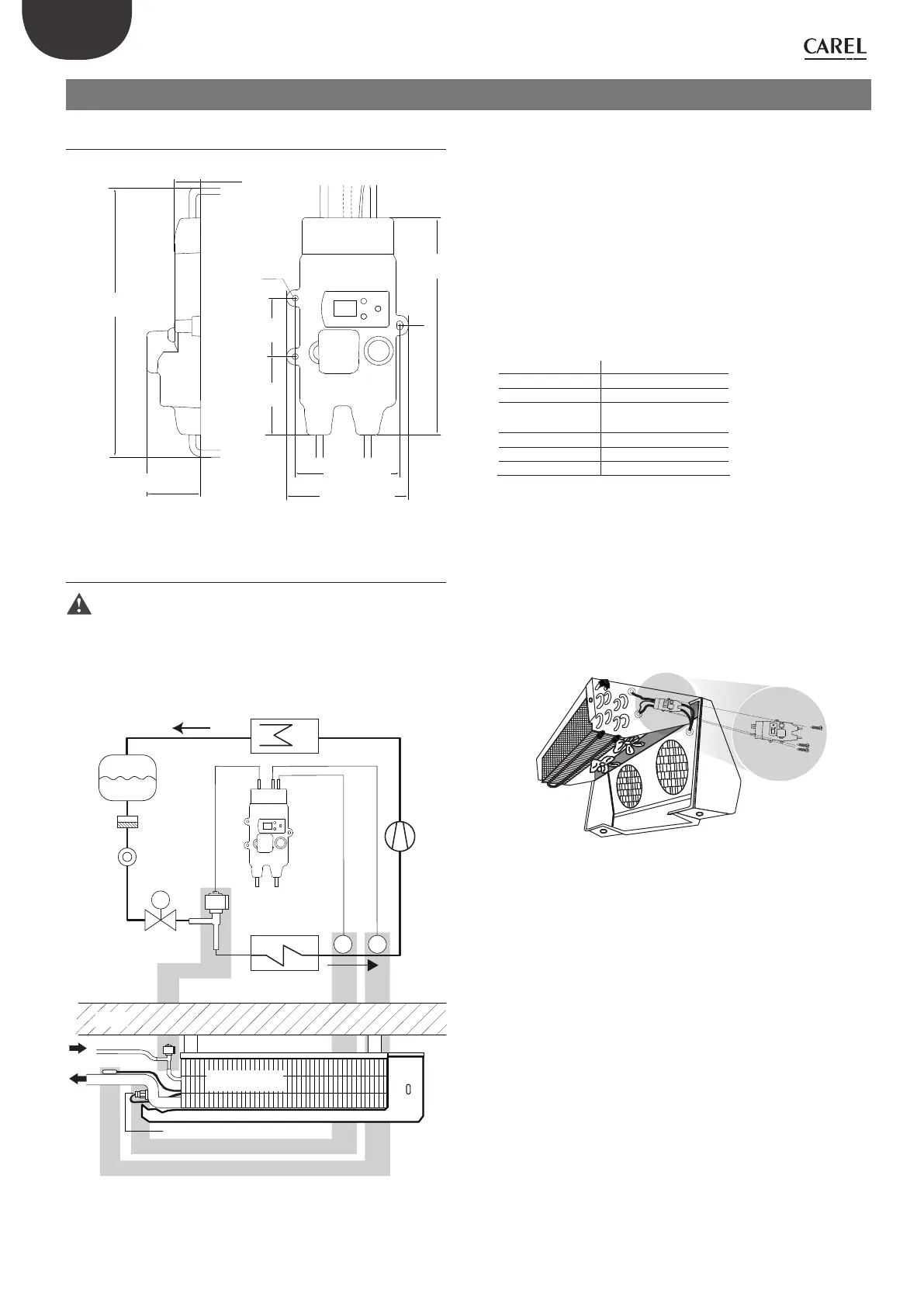
2.1 Dimensions - mm (in)
79.4 (3.1)
92.4 (3.6)
∅
4.5 (0.2)
170 (6.7)
45.5 (1.8)
61.3 (2.4)
40.7(1.6)
19.6 (0.8)
~230 (9.1)
Cable (*) Length (±5%)
Power supply 500 (19.7)
RS485 500 (19.7)
Pressure probe 800 (31.5) --> E2V
1800 (70.9) --> E3V
NTC probe 1800 (70.9)
E2V/ E3V valve 600 (23.6)
Ultracap 100 (3.9)
(*)= for standard CAREL part numbers
Fig. 2.a
2.2 Assembly on the evaporator
Important:
• install EVD ice on the evaporator away from the places where
ice forms;
• connect the power and serial cables in the IP65 junction box;
• for assembly of the E2V/ E3V valve, see the “ ExV system” guide
(+030220810).
Ratiometric pressure transducer
Evaporator
Solenoid
valve
Liquid
indicator
Filter
Liquid
separator
M
Condenser
EVD ice
E2V/ E3V Unipolar
expansion valve
Evaporator unit
NTC temp. probe
Compressor
P T
WALL
Fig. 2.b
EVD ice can be installed directly on the evaporator. Mark the position and
drill the holes (Ø <4.5 mm). Then tighten the fastening screws.
Fig. 2.c

 Loading...