pCO Sistema
Code: +030220336 - rel. 1.5 - 22/12/10
8
2. DESCRIPTION OF THE PRODUCTS
2.1 pCO
3
controller
Rx-/Tx-
Rx+/Tx+
GND
C1
NO1
NO2
NO3
C1
C4
NO4
NO5
NO6
C4
C7
NO7
C7
NO8
C8
NC8
NO12
C12
NC12
NO13
C13
NC13
C9
NO9
NO10
NO11
C9
G
G0
B1
B2
B3
GND
+VDC
+V
term
GND
+5 V
REF
B4
BC4
B5
BC5
VG
VG0
Y1
Y2
Y3
Y4
ID1
ID2
ID3
ID4
ID5
ID6
ID7
ID8
IDC1
B6
B7
B8
GND
ID9
ID10
ID11
ID12
IDC9
ID13H
ID13
IDC13
ID14
ID14H
J1
10
1
11
J24 J2 J3
J4 J5 J7
J8
J20
J21
J14
J11
J10J9
J13J12
J22
J16 J17
J18J15
J23
J6
J19
3
7
7
4
4
6
5
NO14
C14
NC14
NO15
C15
NC15
C16
NO16
NO17
NO18
C16
E-
E+
GND
8
9
2
13
ID15H
ID15
IDC15
ID16
ID16H
Y5
Y6
ID17
ID18
IDC17
B9
BC9
B10
BC10
15
14
field card serial card
8
6
5
7
12
11
16
input: 24 V / ; 50 to 60 Hz
max. power: 40 VA /15W
J20 J25
J21
J22 J23
J19
C14
NC14
NC15
NC16
C14
C17
NC17
NC18
NC19
NC20
C17
E-
E+
GN D
B9
B10
BC9
C25
NC25
NC26
NC27
C25
C21
NC21
NC22
NC23
NC24
C21
5
12
11
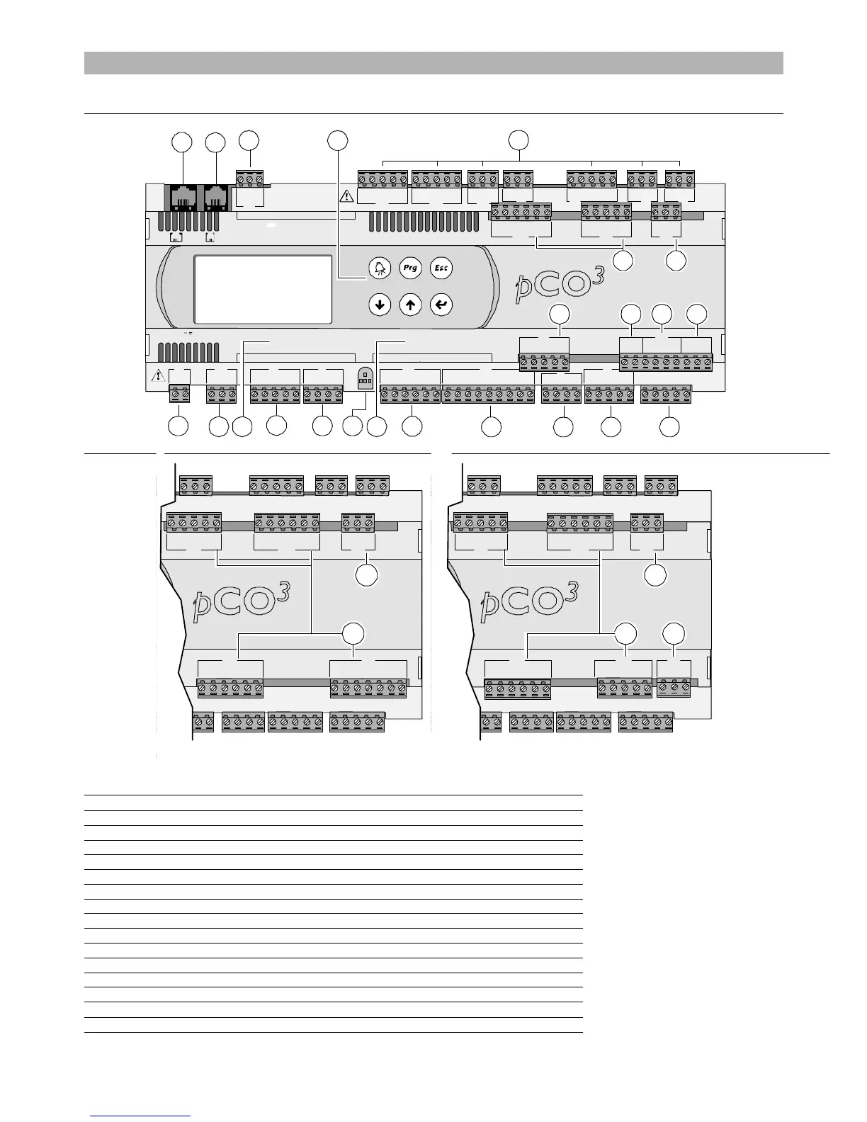
Fig. 2.a
Fig. 2.aFig. 2.a
Fig. 2.a
Key:
Key:Key:
Key:
1. power supply connector [G (+), G0 (-)];
2. yellow power LED and 3 status LEDs (see paragraph 6.3);
3. additional power supply for the terminal and 0 to 5 V ratiometric probes;
4. universal analogue inputs: NTC, 0 to 1 V, 0 to 5 V ratiometric, 0 to 10 V, 0 to 20 mA, 4 to 20 mA;
5. passive analogue inputs: NTC, PT1000, ON/OFF;
6. 0 to 10 V analogue outputs;
7. 24 Vac/Vdc digital inputs;
8. 230 Vac or 24 Vac/Vdc digital inputs;
9. connector for the display panel (external panel with direct signals);
10. connector for all standard pCO series terminals and for downloading the application program;
11. relay digital outputs;
12. connector for connection to the I/O expansion board;
13. pLAN network connector;
14. cover for inserting the supervisor and telemaintenance option;
15. cover for inserting the field card option;
16. Built-In terminal (LCD, buttons and LEDs).

 Loading...


