Standard Shelter
Cod. +030221471 – Rel. 2.0 – April 01, 2003
21
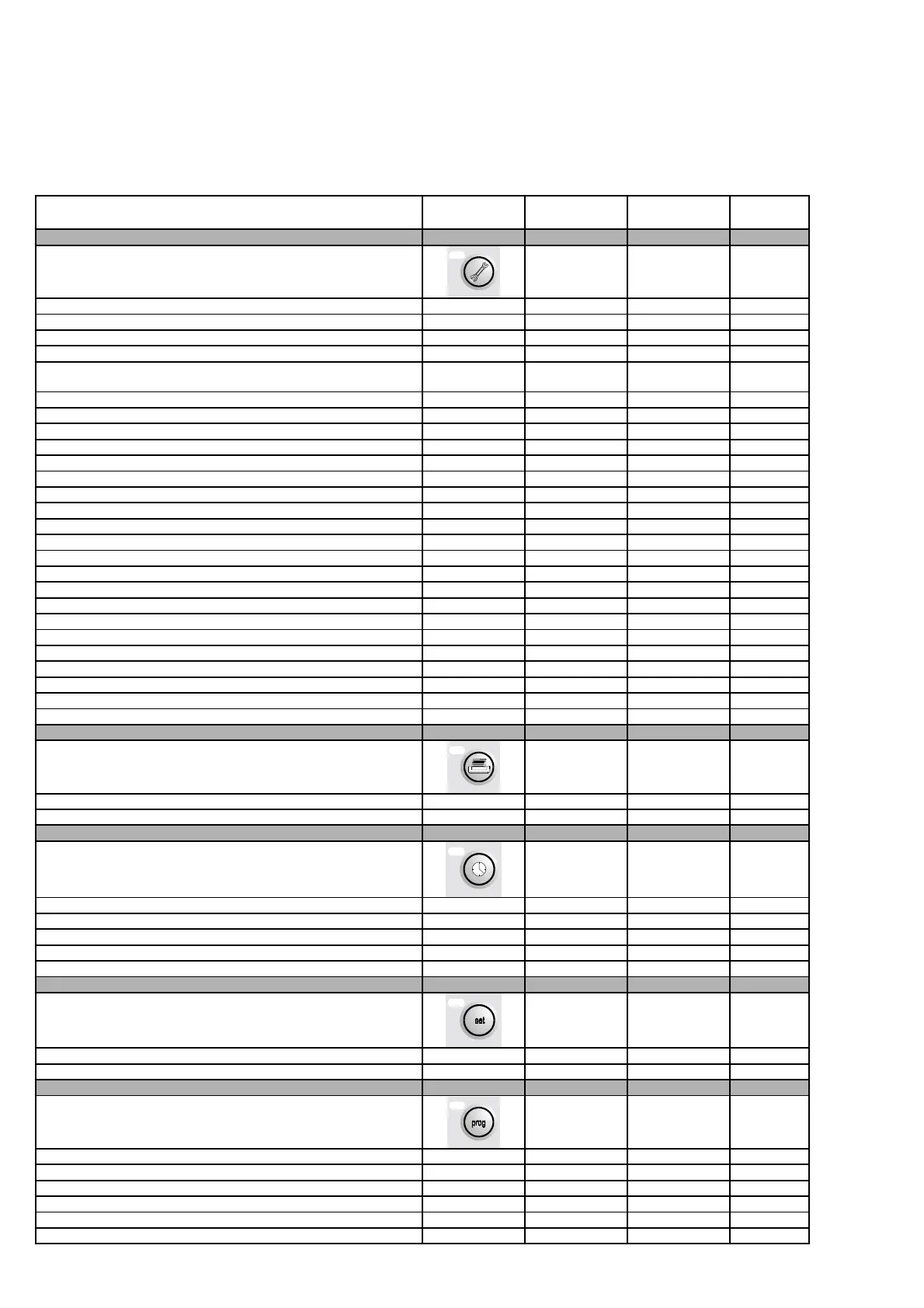
14 LIST OF PARAMETERS AND DEFAULT VALUES
The table below lists the parameters in the program, together with the following information: screen code (the screen code is displayed at the top
right) to assist the identification of the parameter, the default value, the minimum and maximum limits (range), and the unit of measure.
To find a specific parameter on the display, proceed as follows:
• Identify the parameter in the table below and the corresponding screen code
• Using the list of the screens (following paragraph) and the screen code, access the screen on the terminal
DESCRIPTION OF THE PARAMETER SCREEN DEFAULT
VALUE
RANGE UOM
Enter password 1234 0-9999
Modify outlet fan operating hours A6 0 0-99 . 0-999 hours
Modify compressor 1 operating hours A6 0 0-99 . 0-999 hours
Modify compressor 2 operating hours A6 0 0-99 . 0-999 hours
Device operating hour threshold A7 99 0-99 hours x
1000
Cond. 1 pressure probe calibration A8 0 -9.9 - 9.9 %RH
Cond. 2 pressure probe calibration A8 0 -9.9 - 9.9 bar
Humidity probe calibration A8 0 -9.9 - 9.9 bar
Room temperature probe calibration A9 0 -9.9 - 9.9 ºC / ºF
Outside temperature probe calibration A9 0 -9.9 - 9.9 ºC / ºF
Outlet temperature probe calibration A9 0 -9.9 - 9.9 ºC / ºF
Cond. 1 temperature probe calibration Aa 0 -9.9 - 9.9 ºC / ºF
Cond. 2 temperature probe calibration Aa 0 -9.9 - 9.9 ºC / ºF
Manual activation of digital outputs 1 – 2 – 3 Ab Off Off-On
Manual activation of digital outputs 4 – 5 Ac Off Off-On
Manual activation of digital outputs 6 – 7 – 8 Ad Off Off-On
Manual activation of digital outputs 9 – 10 – 11 Ae Off Off-On
Manual activation of modulating outputs 1 – 2 Af 0 0-10.0 Volt
Manual activation of modulating outputs 3 – 4 Ag 0 0-10.0 Volt
Driver 1 valve control mode Ah Automatic Auto-Man.
Driver 1 valve manual opening steps Ah 0 0-9999 Steps
Driver 2 valve control mode Ai Automatic Auto-Man.
Driver 2 valve manual opening steps Ai 0 0-9999 Steps
Driver 1 manual release on start-up Aj No No-Yes
Driver 2 manual release on start-up Ak No No-Yes
Enter new Maintenance password 1234 0-9999
Cyclical print interval H0 24 0-999 hours
Send immediate print H1 No No-Yes
Hour setting K0 current hours 0-23 Hours
Minute setting K0 current minutes 0-59 minutes
Day setting K0 current day 1-31
Month setting K0 current month 1-12
Year setting L0 current year 0-99
Temperature set point S1 23.0 see S1 ºC / ºF
Humidity set point S1 50.0 see S2 %RH
Enter user password 1234 0-9999
Minimum and maximum temperature set point limits P1 -99.9 / 99.9 -999.9 - 999.9 ºC / ºF
Minimum and maximum humidity set point limits P2 0.0 / 100.0 0.0-100.0 %RH
Proportional temperature bands in Heating and cooling P3 3.0 / 3.0 0.0-100.0 ºC / ºF
Temperature dead zone P3 0.0 0.0-99.9 ºC / ºF
Proportional bands in Humidification and Dehumidification P4 2.0 / 2.0 0.0-99.9 %RH
 Loading...


