BEFORE INITIAL START-UP
Job Data Required
• list of applicable design temperatures and pressures (prod-
uct data submittal)
• machine certified drawings
• starting equipment details and wiring diagrams
• diagrams and instructions for special controls or options
• 17/19EX Installation Instructions
• pumpout unit instructions
Equipment Required
• mechanic’s tools (refrigeration)
• digital volt-ohmmeter (DVM)
• clamp-on ammeter
• electronic leak detector
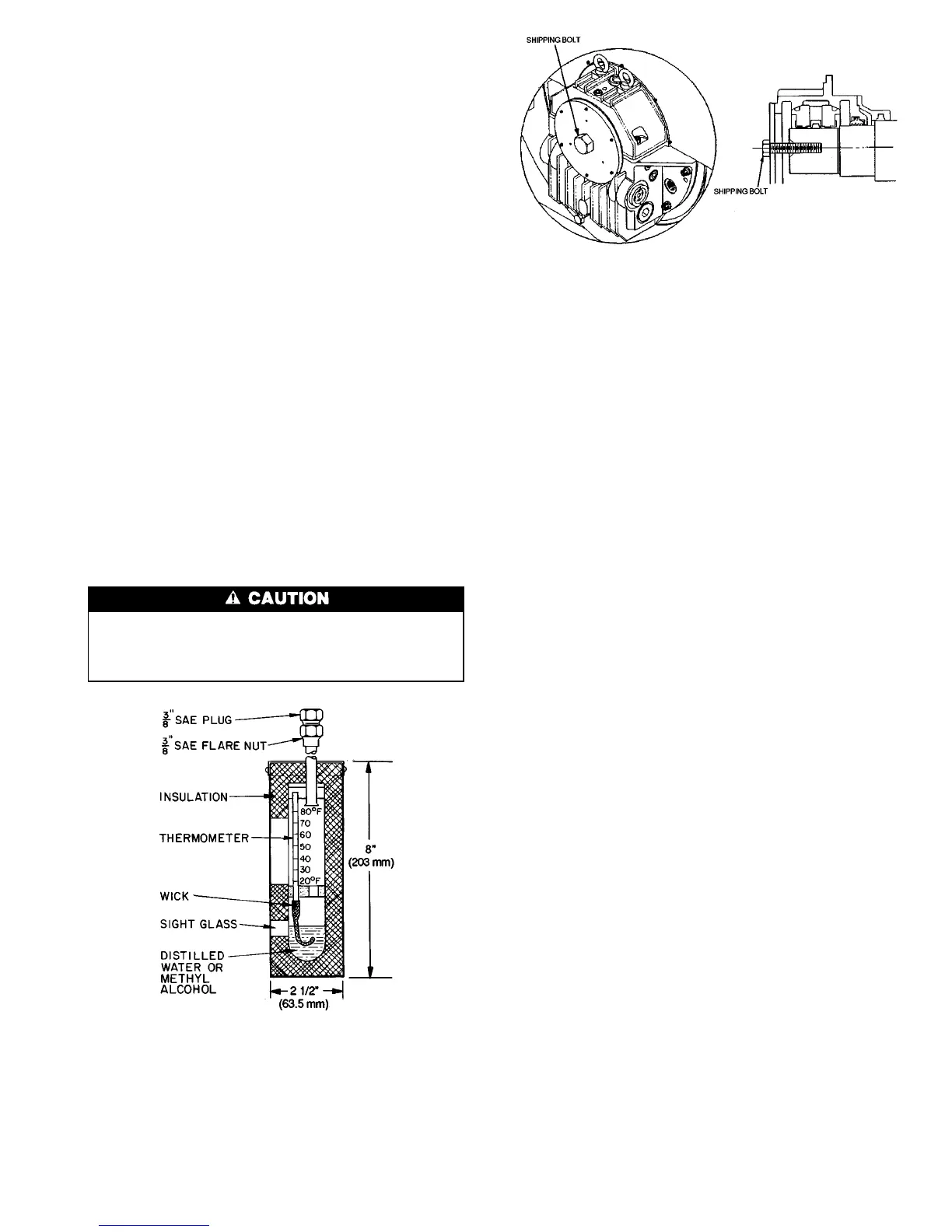
• absolute pressure manometer or wet-bulb vacuum indica-
tor (Fig. 26)
• 500 v insulation tester (megohmmeter) for compressor mo-
tors with nameplate voltage of 600 v or less, or a
5000-v insulation tester for compressor motor rated above
600 v
Using the Utility Vessel and Pumpout System
—
Refer to Pumpout and Refrigerant Transfer Procedures
section, page 64 for: pumpout system preparation, refriger-
ant transfer, and machine evacuation.
Remove Shipping Packaging — Remove any pack-
aging material from the control center, power panel, guide
vane actuator, motor cooling and oil reclaim solenoids, mo-
tor and bearing temperature sensor covers, and the factory-
mounted starter.
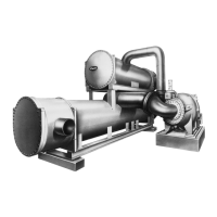
OPEN DRIVE MOTOR
The motor may be provided with a shipping brace or
shipping bolt (normally painted yellow) to prevent shaft
movement during transit. It must be removed prior to
operation. See Fig. 27.
The motor should be inspected for any temporary, yellow
caution tags whose legends convey information concerning
actions necessary before the motor can be safely operated.
Any slushing compound on the shaft or other parts must be
removed using a petroleum type solvent and observing proper
safety precautions.
NOTE: If the motor utilized a shipping bolt for restraining
the rotor, the Westinghouse logo must be installed over the
hole in the endcover. The logo, the gasket, and hardware can
be found with the parts that have been shipped loose. (Usu-
ally these are packed inside of the main power lead box.)
Open-Drive Motor Electrical Connection — All
interconnecting wiring for controls and grounding should be
in strict accordance with both the National Electrical Code
and any local requirements.
The main lead box furnished with the motor has been sized
to provide adequate space for the make-up of the connec-
tions between the motor lead cables and the incoming power
cables. The bolted joints between the motor lead and the power
cables must be made and insulated in a workman-like man-
ner following the best trade practices.
Fabricated motors are provided with 2 stainless steel ground-
ing pads drilled and tapped with the NEMA 2-hole pattern
(two
1
⁄
2
-13 tapped holes on 1
3
⁄
4
in. centers). Fan cooled cast
frames are provided with a special grounding bolt. The mo-
tor should be grounded by a proper connection to the elec-
trical system ground.
The rotation direction of the motor will be as shown by
either a nameplate on the motor or the certified drawing. The
required phase rotation of the incoming power for this motor
rotation may also be stated. If either is unknown, the correct
sequence can be determined in the following manner: While
the motor is uncoupled from the load, start the motor and
observe the direction of rotation. Allow the motor to achieve
full speed before disconnecting it from the power source.
Refer to Open-Drive Motor Pre-Start Checks (page 53) for
information concerning initial start-up. If resulting rotation
is incorrect, it can be reversed by interchanging any 2 in-
coming cables.
Fig. 27 — Shipping Bolt on Open Drive Motor
Fig. 26 — Typical Wet-Bulb Type
Vacuum Indicator
47
 Loading...