17
TROUBLESHOOTING
Systems Communication Failure
If communication is lost with the User Interface (UI), the control
will flash the appropriate fault code (see Table 7). Check the wiring
to the User Interface and the indoor and outdoor units and power.
Model Plug
Each control board contains a model plug. The correct model plug
must be installed for the system to operate properly (see Table 4).
The model plug is used to identify the type and size of unit to the
control.
On new units, the model and serial numbers are inputted into the
AOC
board s memory at the factory. If a model plug is lost or
missing at initial installation, the unit will operate according to the
information input at the factory and the appropriate error code will
flash temporarily. An RCD replacement AOC board contains no
model and serial information. If the factory control board fails, the
model plug must be transferred from the original board to the
replacement board for the unit to operate.
When installing heat pump with older fan coils, a model plug
change may be required. See table 2 for fan coils requiring model
plug change.
NOTE: The model plug takes priority over factory model
information input at the factory. If the model plug is removed after
initial power up, the unit will operate according to the last valid
model plug installed, and flash the appropriate fault code
temporarily.
Table 4 – Factory Supplied Model Plug Information
25VNA8
MODEL PLUG
NUMBER
PIN RESISTANCE
( K --- o h m s )
P i n s 1 --- 4 P i n s 2 --- 3
13 HK70EZ029 11K 220K
24A* 25 HK70EZ001 5.1K 11K
24B* HK70EZ009 5.1K 91K
36 HK70EZ002 5.1K 18K
37 HK70EZ026 11K 120K
48 HK70EZ003 5.1K 24K
60 HK70EZ004 5.1K 33K
* 24A unit height is 38---7/16” and 24B unit height is 31---5/ 8”
Service Tool
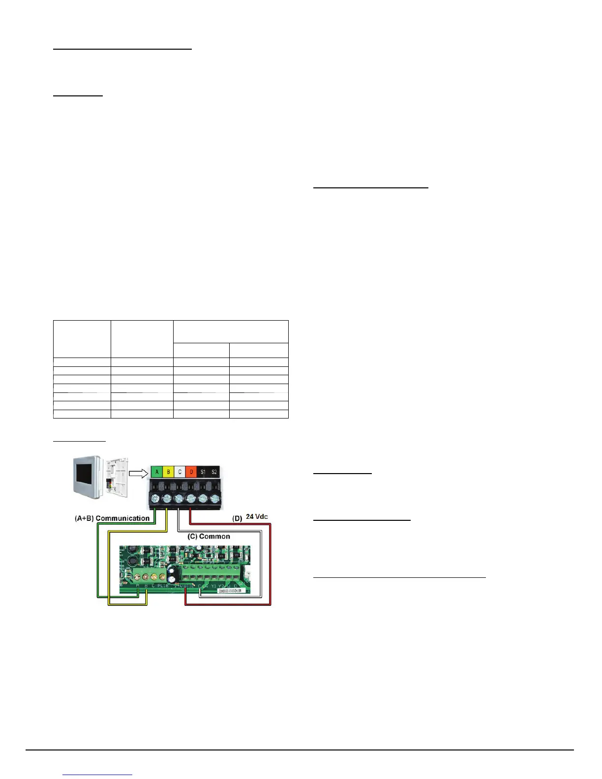
A150062
Fig. 35 -- Service Tool Connection
When working on the outdoor unit of a split system, the technician
would usually need to repeatedly walk between the indoor wall
control and the unit outside. To save time, the communicating
controls offer a service tool feature.
By wiring the service tool into the AOC board and powering it
with an external adapter, the technician can have a wall control
capable of running the system right at the outdoor unit.
To use a service tool, connect the A and B communication bus
wires from this second communicating control to the terminals
marked A and B on the terminal strip located in the bottom left
corner of the AOC board (see Fig. 35). But instead of connecting
the wires on the service tool to the terminals marked C and D,
connect the C and D wires from the service tool to the 24V and C
on ST1 as shown in Fig. 35.
When the service tool is connected and powered up, the
communicating controls inside the home will ”go to sleep” and let
the service tool take control of the system. In this manner, the
service technician can run the diagnostic checkouts right at the
outdoor unit using the service tool.
After the checkouts are completed and it is no longer necessary to
use the service tool, remove it from the communicating controls
and the indoor communicating controls will regain control in about
two minutes.
Pressure Switch Protection
The outdoor unit is equipped with high pressure switch. If the
control senses the opening of a high pressure switch (open 600+/-- 5
psig, close 470+/--10 psig @77_F), it will respond as follows:
1. Display the appropriate fault code (see Table 7).
2. After a 15 minute delay, if there is a call for cooling or heat-
ing and HPS is reset, the PEV opens for 150 seconds to
equalize system pressures. The compressor and fan will then
ramp to the next lower stage of operation until demand is
satisfied. In the next call for heating/cooling system will re-
sume normal operation.
3. If the opened switch closes at any time after the 15 minute
delay, then the PEV opens for 150 seconds to equalize sys-
tem pressures. The compressor and fan will then ramp to the
next lower stage of operation until demand is satisfied. In
the next call for heating/cooling system will resume normal
operation.
4. If HPS trips 3 consecutive cycles, the unit operation is
locked out for 4 hours.
5. In the event of a high--pressure switch trip or high--pressure
lockout, check the refrigerant charge, outdoor fan operation,
and outdoor coil (in cooling) for airflow restrictions, or in-
door airflow in heating.
6. In the event of a low--pressure trip or low--pressure lockout,
check the refrigerant charge and indoor airflow (cooling)
and outdoor fan operation and outdoor coil in heating.
Control Fault
If the outdoor unit control board has failed, the control will flash
the appropriate fault code (see Table 7). The control board should
be replaced.
Brown--Out Protection
If the line voltage is less than 187V for at least 4 seconds, the
Compressor and OD fan goes to 0 rpm. Compressor and fan
operation are not allowed until voltage is a minimum of 190V. The
control will flash the appropriate fault code (see Table 7).
230V Line (Power Disconnect) Detection
The control board senses the presence of absence of 230V through
inverter feedback. Voltage should present at all times when system
is in service regardless if system is running or standby. If there is
no 230V at the inverter when the indoor unit is powered with a
cooling or heating demand, the appropriate fault code is displayed
on UI (communicating only – see Table 7). If system is configured
with conventional heat pump thermostat (non-- communicating), no
fault code will be displayed on AOC board, nor will any status
LEDs be lit. Use multimeter to check for the presence of 230V in
this situation.
Manufacturer reserves the right to change, at any time, specifications and designs without notice and without obligations .
Catalog No: 25
N
8 --- 5 S I
Replaces: 25VNA8---4SI
 Loading...