8
Step 8 — Compressor Crankcase Heater
This compressor has an internal crankcase heater. Furnish power
to the unit a minimum of 24 hr before starting the unit for the first
time.
Upon initial start--up of unit, status code 68 will be generated and
system will operate at stage 2 for 11 minutes. This operation is
important to system reliability and cannot be bypassed. Each time
high voltage is removed and reapplied this behavior will be
repeated.
To furnish power to heater only, set thermostat to OFF and close
electrical disconnect to outdoor unit.
Power is not required to the indoor unit or User Interface for proper
operation of heater. Crankcase heater will be intelligently
energized as needed between operations, even when the UI or
thermostat and indoor unit is not installed, as long as there is power
to the outdoor unit.
Airflow Setup for Infinity Touch Control Furnace
or FE Fan Coil (communicating)
This system can only be installed with Infinity-- capable indoor and
Infinity Touch User Interface (UI) SYSTXCCITC01,
SYSTXCCITW01 or SYSTXCCITN01 with version 11 software
or newer. Version 12 or newer software required on model size 13.
When using an Infinity Touch User Interface, airflow is
automatically selected based on equipment size. The user has the
option of selecting Comfort, Efficiency and Max airflow for
Heating and/or Cooling modes. These should be selected based on
balance between the homeowner’s comfort and energy
consumption expectations. See User Interface Installation
Instructions for additional available adjustments.
Due to using a communicating control with the fan coil or the
furnace, dip switch adjustments are not necessary. The outdoor
unit configuration and the indoor airflows are determined by
communicating control setup.
Airflow Setup for Non--communicating Fan Coil
The system can be installed with a standard 2--stage heat pump
thermostat and FV4C fan coil without additional accessories.
Select appropriate unit size on fan coil Easy select board.
For replacement applications with older FV4(A,B), FK4 and 40FK
fan coils, the model plug in the outdoor unit must be changed per
Table 2 below.
The model plug adjusts compressor speed to match available low
stage indoor airflow.
NOTE: 25VNA813 is AHRI rated with communicating indoor
units only due to low stage airflow requirements.
Table 2 – Alternate Model Plug
FV4(A,B), FK4, 40FK Fan Coil Models*
(Requires outdoor model plug change)
25VNA8
Factory
Model Plug #
HK70EZ***
Required Accessory
Model Plug #
HK70EZ***
24B{ 009 015
24A{
001 016
25
36 002 017
48 003 018
60 004 019
* FK4 and 40FK also require a TXV change. See accessory list for approved TXV.
{ 24A unit height is 38--- 7/16” a nd 24B unit height is 31--- 5/8”
Airflow Setup for Non--communicating Furnaces
For installations with non--communicating furnaces, set airflows to
350--400 cfm/nominal ton in high stage and 70--80 percent of high
stage airflow in low stage.
Step 9 — Install Accessories
No refrigeration circuit accessories are required or are available for
installation within the unit. External to the unit, the same
accessories such as support feet, snow rack, wind baffle etc.,
available on other Carrier units, can also be used on this line of
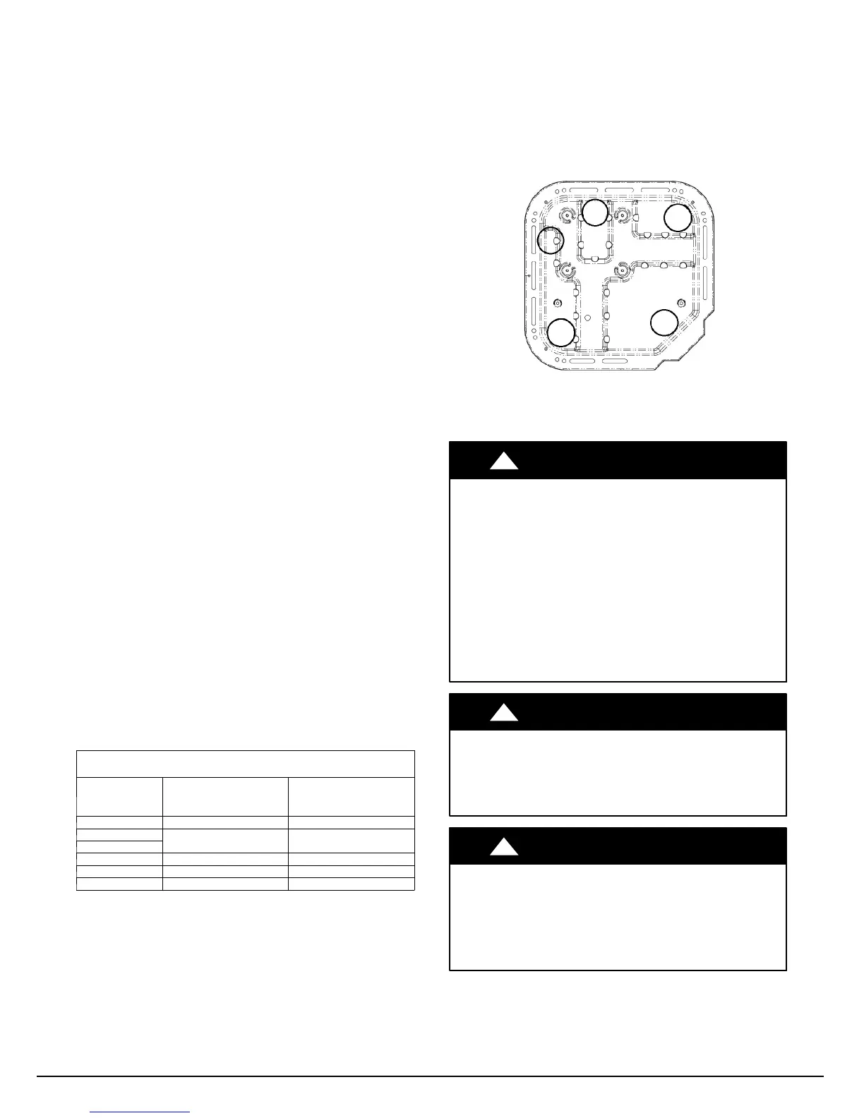
product. For models utilizing 23 inch x 23 inch base pans, it is
recommended to use 5 support feet in order to fully support unit.
See Fig. 9. Refer to the individual Installation Instructions
packaged with kits or accessories when installing.
A14008
Fig. 9 -- Recommended Support Feet Location
(for 23” x 23” basepan)
Step 10 — Start--Up
CAUTION
!
UNIT OPERATION AND SAFETY HAZARD
Failure to follow this caution may result in minor personal
injury, equipment damage or improper operation.
Observe the following:
1.Do not overcharge system with refrigerant.
2.Do not operate unit in a vacuum or at negative pressure.
3.Do not disable low pressure transducer or system safety
devices such as discharge thermistor or the high pressure
switch.
4.Dome temperatures may be hot.
5.Discharge thermistor is engaged tight on the discharge tube.
CAUTION
!
PERSONAL INJURY HAZARD
Failure to follow this caution may result in personal injury.
Wear safety glasses, protective clothing, and gloves when
handling refrigerant.
CAUTION
!
ENVIRONMENTAL HAZARD
Failure to follow this caution may result in environmental
damage.
Federal regulations require that you do not vent refrigerant to
the atmosphere. Recover during system repair or final unit
disposal.
Manufacturer reserves the right to change, at any time, specifications and designs without notice and without obligations .
Catalog No: 25
N
8 --- 5 S I
Replaces: 25VNA8---4SI
 Loading...