3
7. Avoid direct tubing contact with water pipes, duct work,
floor joists, wall studs, floors, and walls.
8. Do not suspend refrigerant tubing from joists and studs with
a rigid wire or strap which comes in direct contact with tub-
ing (see Fig. 1).
9. Ensure that tubing insulation is pliable and completely sur-
rounds vapor tube.
10. When necessary, use hanger straps which are 1 in. wide and
conform to shape of tubing insulation. (See Fig. 1.)
11. Isolate hanger straps from insulation by using metal sleeves
bent to conform to shape of insulation.
12. If these installation recommendations were not followed,
gas pulsation may be transmitted through improperly
mounted line sets. In this case, an external vapor line muf-
fler accessory (part no. LM10KK003) is available to mini-
mize noise due to gas pulsations.
EQUIPMENT DAMAGE HAZARD
Failure to follow this caution may result in equipment damage.
If proper lineset routing techniques are not followed, variable
speed systems can be susceptible to lineset transmitted noise
inside the dwelling and, in extreme cases, tubing breakage.
CAUTION
!
INSULATION
SUCTION TUBE
LIQUID TUBE
OUTDOOR WALL INDOOR WALL
LIQUID TUBE
SUCTION TUBE
INSULATION
CAULK
HANGER STRAP
(AROUND SUCTION
TUBE ONLY)
JOIST
1” (25.4 mm)
MIN
THROUGH THE WALL
SUSPENSION
A07588
Fig. 1 -- Connecting Tubing Installation
The outdoor unit contains the correct amount of refrigerant charge
for operation with AHRI rated indoor units when connected by 15
ft (4.57 m) of field--supplied or factory accessory tubing.
Adjust refrigerant charge by adding or removing the charge
to/from the unit depending on lineset length and indoor unit as
calculated and displayed on the UI. The user interface (UI)
calculates required charge adjustment and total system charge
required. For proper unit operation, check refrigerant charge using
charging information in the Check Char ge section of this
instruction.
IMPORTANT: Liquid--line size is 3/8 --in. OD for all 25VNA8
applications. The maximum allowable equivalent line set length is
100 ft. (30.5 m).
IMPORTANT: Always install the factory --supplied liquid --line
filter drier. Obtain replacement filter driers from your distributor or
branch.
INSTALLATION
Specifications for this unit in residential new construction market
require the outdoor unit, indoor unit (including metering device),
refrigerant tubing sets, and filter drier listed in pre--sale literature.
There can be no deviation. Consult the Service Manual – Air
Conditioners and Heat Pumps Using Puron Refrigerant to obtain
required unit changes for specific applications and for R--22
retrofit.
Step 1 — Check Equipment and Job Site
Unpack Unit
Move to final location. Remove carton taking care not to damage
unit.
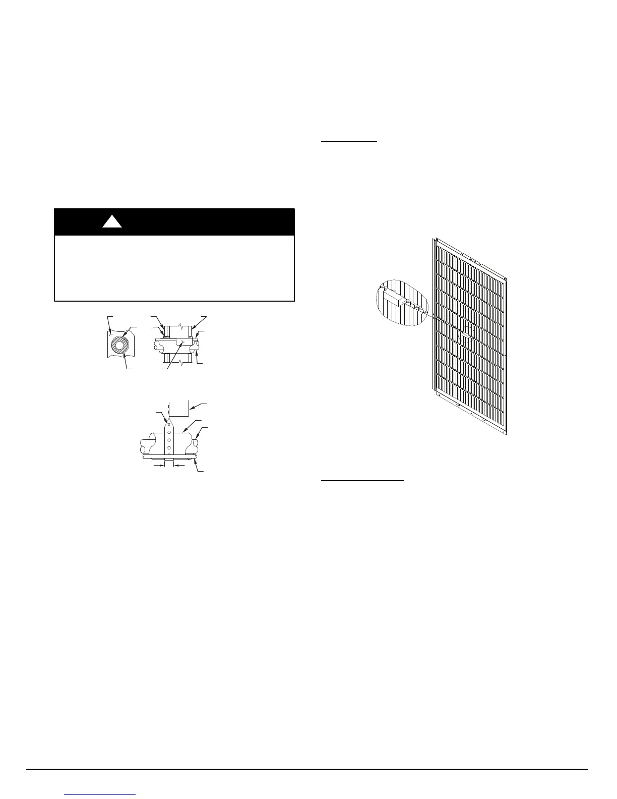
This unit employs one louver spacer on each of the four sides to
prevent louver movement during operation. The louver spacers are
trapped between the coil surface and louver at the approximate
center of each side (See Fig. 2). This louver spacer should be
present and, if dislodged during shipment, must be reinstalled
before unit is placed into operation.
A11380a
Fig. 2 -- Louver Spacer Location
Inspect Equipment
File claim with shipping company prior to installation if shipment
is damaged or incomplete. Locate unit rating plate on unit corner
panel. It contains information needed to properly install unit.
Check rating plate to be sure unit matches job specifications.
Step 2 — Install on a Solid, Level Mounting Pad
If conditions or local codes require the unit be attached to pad, tie
down bolts should be used and fastened through knockouts
provided in unit base pan. Refer to unit mounting pattern in Fig. 3
to determine base pan size and knockout hole location.
For hurricane tie downs, contact distributor for details and PE
(Professional Engineer) Certification, if required.
On rooftop applications, mount on level platform or frame. Place
unit above a load--bearing wall and isolate unit and tubing set from
structure. Arrange supporting members to adequately support unit
and minimize transmission of vibration to building. Consult local
codes governing rooftop applications.
Roof mounted units exposed to winds above 5 mph may require
wind baffles. Consult the Service Manual -- Residential Split
System Air Conditioners and Heat Pumps Using Puron
Refrigerant for wind baffle construction.
NOTE: Unit must be level to within 2 (3/8 in./ft,9.5 mm/m.)
per compressor manufacturer specifications.
Manufacturer reserves the right to change, at any time, specifications and designs without notice and without obligations .
Catalog No: 25
N
8 --- 5 S I
Replaces: 25VNA8---4SI
 Loading...