21
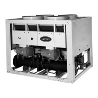
Example: SI — Determine concentration of inhibited
ethylene glycol to protect the system to –23 C ambient
temperature at zero flow.
Enter the solution crystallization point curve above,
at –23 C, read 40% concentration inhibited ethylene
glycol is required to prevent crystals from forming in
solution.
Consider 30GTN110 unit selected from the Selection
Procedure example (refer to correction curves at 40%
solution).
Correct unit capacity — On glycol performance
capacity correction curve above, read 0.95.
Corrected capacity = 0.95 x determined capacity
= 0.95 x 379.7
= 360.7 kW
Correct chilled water flow — On cooler flow
correction
curve above, read 1.15.
Chilled water flow (at corrected capacity)
= 0.239 x corr. cap. in kW = L/s
temperature rise C
= 0.239 x 360.7 = 11.1 L/s
7.8°
Chilled water flow (40% solution) = 1.15 x 11.1
= 12.8 L/s
Correct cooler pressure drop — On cooler pressure drop
correction curve on this page, read 1.33.
On cooler pressure drop curve on page 49, for 12.8 L/s,
read pressure drop of 24 kPa. The pressure drop for 40%
solution = 1.33 x 24 = 31.92 kPa.
Correct compressor power input (kW) — On the power
correction curve on this page, read 0.97 correction factor
at 40% ethylene glycol concentration.
Power input from Selection Procedure example
= 123.2 kW.
Corrected power input = 0.97 x 123.2 = 119.5 kW.
Oversizing chillers
Oversizing chillers by more than 15% at design conditions
must be avoided as the system operating efficiency is
adversely affected (resulting in greater or excessive
electrical demand). When future expansion of equipment is
anticipated, install a single chiller to meet present load
requirements and add a second chiller to meet the additional
load demand.
It is also recommended that 2 smaller chillers be installed
where operation at minimum load is critical. The operation
of a smaller chiller loaded to a greater percentage ove
its minimum recommended value.
Hot gas bypass should not be used as a means to allow
oversizing chillers. Hot gas bypass should be given
consideration where substantial operating time is anticipated
below the minimum unloading step.
Multiple chillers
Where chiller capacities greater than 200 tons (703 kW) are
required, or where stand-by capability is desired, chillers
may be installed in parallel. Units should be of equal size to
ensure balanced fluid flows. Where a large temperature drop
(> 25° F [13.9° C]) is desired, chillers may be installed in
series. Fluid temperature sensors need not be moved for
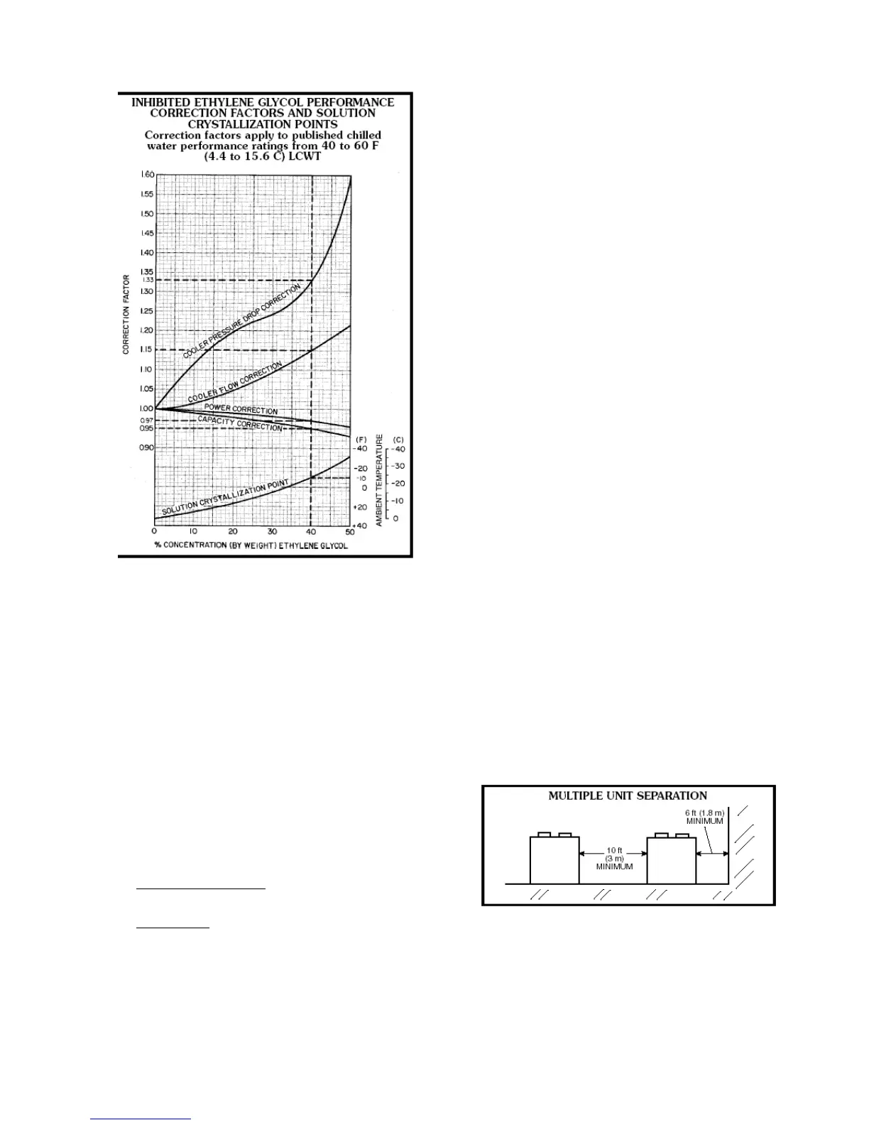
multiple chiller operation. A 10 ft (3 m) separation is
required between units for airflow, and a 6 ft (1.8 m)
distance is required from units to obstructions. See Multiple
Unit Separation figure below. See Base Unit Dimensions
section on pages 27-39 for service clearances.
Unit software is capable of controlling two units as a
single plant. Refer to Controls, Start-Up, Operation, Service,
and Troubleshooting guide for further details.

 Loading...