18
Application data
MINIMUM COOLER FLUID FLOW RATES
AND MINIMUM LOOP VOLUME
Leveling unit
Unit must be level within 1/8-in. per ft when installed to
ensure proper oil return to the compressors.
While most outdoor locations are suitable for 30GTN,GTR,
GBN,GBR units, the roof is a common site that presents a
problem if roof has been pitched to aid in water removal. To
assure proper oil return, be sure that unit is level, particularly
in its major lengthwise dimension, as compressor oil return
piping runs in that direction.
t should be determined prior to installation if any specia
treatment is required to assure a level installation.
Cooler fluid temperature
1. Maximum leaving chilled fluid temperature (LCWT) for
unit is 70 F (21 C). Unit can start and pull down with up
to 95 F (35 C) entering-fluid temperature due to MOP
(maximum operating pressure) feature of the TXV. For
sustained operation, it is recommended that entering-fluid
temperature not exceed 85 F (29.4 C).
2. Minimum LCWT for standard unit is 40 F (3.3 C). It is
permissible to use a standard microprocessor-controlled
ComfortLink™ chiller with leaving-fluid temperatures in
the range of 34 to 39.9 F (1° to 3.28 C) only if a
protective brine solution (20% antifreeze solution, or
greater) is used. (See Controls and Troubleshooting
literature for further information.)
Medium temperature brine application
Application of chiller for brine duty within the 39.9 to 15 F
(3.3 to –9.4 C) range is possible by ordering the proper
factory-installed brine option. For ratings below 38° F (3.3
C) LCWT, contact your local Carrier representative.
Leaving-fluid temperature reset
Reset reduces compressor power usage at part load when
design LCWT is not necessary. Humidity control should be
considered since higher coil temperatures resulting from
reset will reduce latent heat capacity. Three reset options are
offered, based on the following:
Return-fluid temperature — Increases LCWT temperature
set point as return (or entering) fluid temperature decreases
(indicating load decrease). Option may be used in any
application where return fluid provides accurate load
indication. Limitation of return fluid reset is that LCWT may
only be reset to value of design return fluid temperature.
Outdoor-air temperature — Increases LCWT as outdoo
ambient temperature decreases (indicating load decrease).
This reset should be applied only where outdoor ambient
temperature is an accurate indication of load. An accessory
thermistor is required.
Space temperature — Increases LCWT as space
temperature decreases (indicating load decrease). This reset
should be applied only where space temperature is an
accurate indication of load. An accessory thermistor is
required.
For details on applying a reset option, refer to uni
Controls and Troubleshooting literature. Obtain ordering
part numbers for reset option from current price pages or
contact your local Carrier representative.
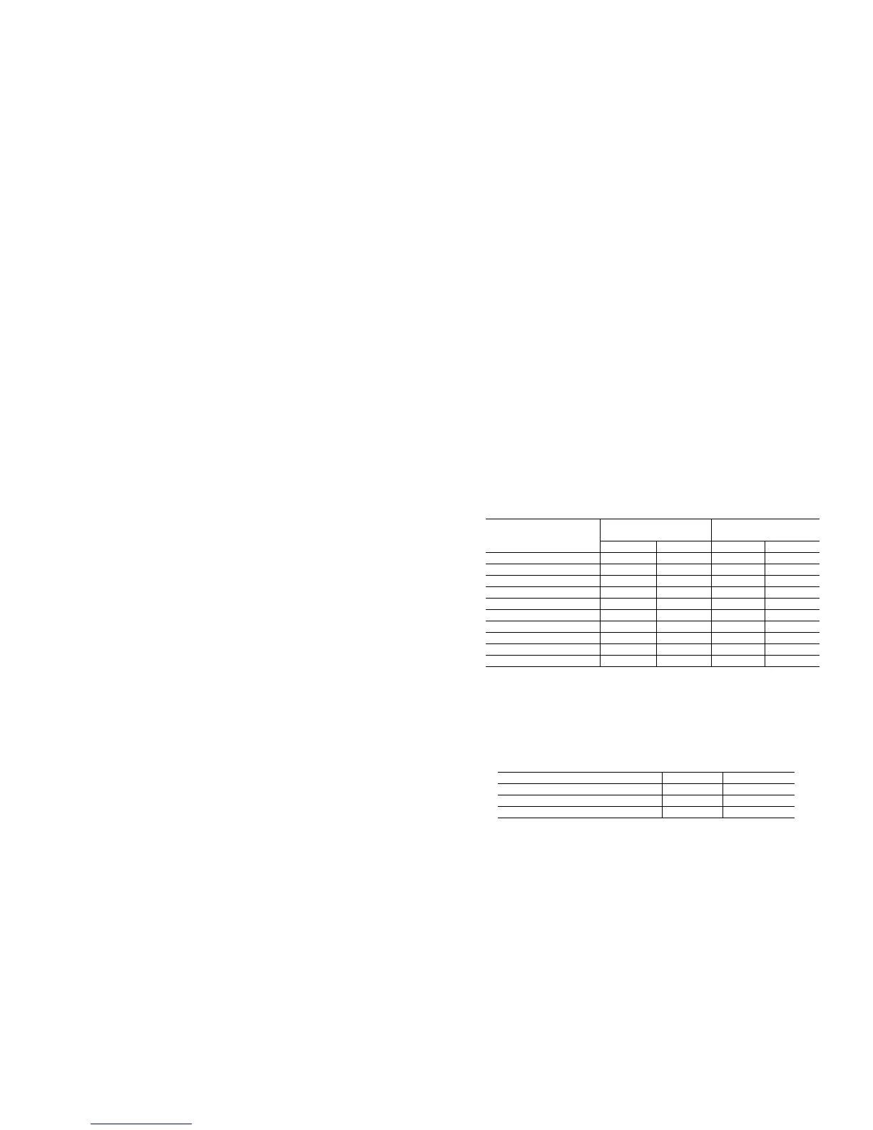
Cooler flow range
Ratings and performance data in this publication are for
a cooling temperature rise of 10° F (6° C), and are
suitable for a range from 5 to 20 F (2.8 to 11.1 C)
temperature rise without adjustment. The ComfortLin
chillers may be operated using a different temperature
range, provided flow limits are not exceeded. Fo
minimum flow rates, see Minimum Cooler Fluid Flow
Rates and Minimum Loop Volume table. High flow rate
is limited by pressure drop that can be tolerated. I
another temperature range is used, apply LCWT
correction as given in Selection Procedure example on
page 53.
APPLICATION V N
Normal Air Conditioning 33.25
Process Type Cooling 6 to 10 6.5 to 10.8
Low Ambient Unit Operation 6 to 10 6.5 to 10.8
NOTES:
1. Minimum flow based on 1.0 fps (0.30 m/s) velocity in cooler without special
cooler baffling.
2. Minimum Loop Volumes:
Gallons = V x ARI Cap. in tons
Liters = N x ARI Cap. in kW
MINIMUM COOLER
FLOW RATE
MINIMUM LOOP
VOLUME
UNIT SIZE
30GTN,GTR,GBN,GBR
Gpm L/s Gal L
050 37.7 2.38 153 580
060 47.5 3.00 181 684
070 47.5 3.00 210 796
080 66.7 4.20 243 920
090 59.5 3.75 272 1029
100 84.1 5.30 301 1138
110 81.1 5.30 333 1260
150, 300A/B 192.0 6.90 502 1900
175, 350A/B 192.0 6.90 568 2150
200, 400A/B 192.0 6.90 635 2403
 Loading...